- 9 -
Service Manual
Model No.: 48E2500
3-2-1 Function Description
Process signal which incept from exterior equipment then translate into signal that panel
can display.
3-2-2 Connector Definition
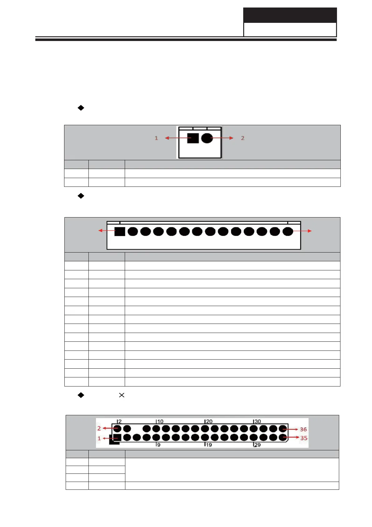
CNB2(2PIN/2.0): POWER SUPPLY FOR UPGRADE
CONNECTOR
NO. SYMBOL DESCRIPTION
1GND Ground
212V +12VDCPowerSupply
CN6(14PIN/2.0): IR& KEY BOARD CONNECTOR
NO. SYMBOL DESCRIPTION
1GND Ground
2K7 Key7(Reserved)
3K6 Key6
4K5 Key5
5K4 Key4
6K3 Key3
7K2 Key2
8K1 Key1
9K0 Key0
10 GND Ground
11 IR IR Receiver
12 GRN Green Indicator
13 RED Red Indicator
14 5V +5V DC Power Supply
CN5(2h18PIN/2.0): LVDS INTERFACE
Note: PIN31~40 are optional. The connector or each PIN can refer to the panel specification.
NO. SYMBOL DESCRIPTION
1VSEL
Power Supply for Panel
2VSEL
3VSEL
4GND Ground
141