12
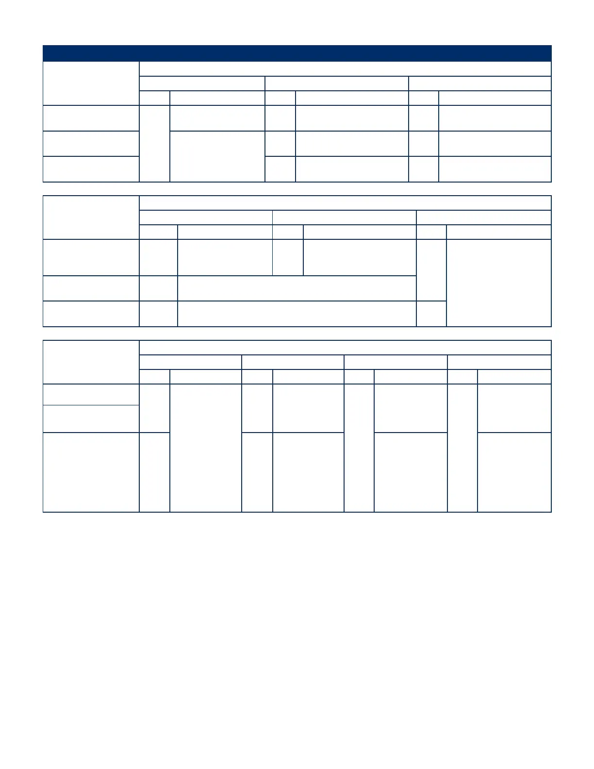
Displays and Indicators
STATE
PARAMETER
RF/Stimulus Output FAULT indicator RF/Stimulus Output ON/OFF indicator
Status Description Status Description Status Description
System Initialization
OFF
No RF or stimulus waveforms
are generated.
OFF
Only Power On is illuminated during
Initialization.
OFF
Only Power On is illuminated during
Initialization.
Power-On-Self-Test (POST)
RF and stimulus waveforms
are delivered into internal test
loads.
The output is inactive.
ON
All indicators are illuminated during
POST.
ON
All indicators are illuminated during
POST.
STANDBY OFF
(The FAULT indicator is used only in
the POST and SYSTEM FAULT states.)
OFF
The indicator is not illuminated
during this state.
STATE
PARAMETER
RF Audio Output Impedance Related Audio Output Graph Window
Status Description Status Description Status Description
System Initialization OFF
RF audio output is
not generated during
Initialization.
OFF
Impedance related audio output is
not generated during Initialization.
N/A
No parameters are graphed
during this state.Power-On-Self-Test (POST)
ON-POST
tone
A tone sounds for approximately 2 seconds to indicate that the system is active
and is performing self-tests. The tone also serves as a test of the audio output.
STANDBY None N/A None
STATE
PARAMETERS
Measurement Window Status Window Available States Available Settings
Status Description Status Description Status Description Status Description
System Initialization
N/A
No parameters are
measured during this
state.
None N/A
None
No other modes are
available during
Initialization and POST
states.
None
No settings are
available during this
state.
Power-On-Self-Test (POST)
STANDBY None Active
“PLEASE ATTACH
PROBE TO CABLE THEN
ATTACH CABLE TO
GENERATOR” message
is displayed while in
the STANDBY mode.
No operating modes
are available until a
probe is connected.
The ADVANCED
SETTINGS mode can
be entered during the
STANDBY state.
N/A
7.2 PLACEMENT State
• In the TRANSDISCAL mode, TREATMENT state is the default screen upon connection of a valid TRANSDISCAL* Cable and probe, or when a TRANSDISCAL* Y-Connecting Cable
is used. The PLACEMENT state can be accessed from the STIMULATION or TREATMENT READY states. The PLACEMENT state cannot be accessed during the STIMULATION ON or
TREATMENT ON states.
When in the PLACEMENT state:
• MEASURING TDP A is the default screen when the switching cable is set to Probe A, or when a TRANSDISCAL* Y-Connecting Cable is used.
• MEASURING TDP B is the default screen when the switching cable is set to Probe B and BIPOLAR is enabled for use in the TRANSDISCAL mode, accessible from the
ADVANCED SETTINGS mode.
Avanos Exhibit 2069 Page 12
Medtronic, Inc. v. Avanos Medical Sales, LLC
Case IPR2020-0089