27
Settings
Aected Mode Parameter DESCRIPTION Range/Units Default Value Increment
Auto Temp LESION RAMP TIME Ramp-up interval to temperature set point. 10–60 s 15 s 1 s
AUTO TEMP LESION,
AUTO PULSED LESION
POWER LIMIT Maximum allowable power for temperature control. 1–50 W 50 W 1 W
AUTO PULSED LESION RAMP TIME Ramp-up interval to temperature set point. 5–60 s 15 s 1 s
MULTI-RF
TEMPERATURES
DISPLAYED
Temperature displayed on screen in Multi-RF mode Measurement Window
and Graph Display.
ALL/MAX ALL N/A
MULTI-RF (TRUE-TX)
MAX RAMP TIME
EXTENSION
Maximum allowable duration for extension of ramp time. If all probes have
not reached Set Temperature within this time, an error notication will be
generated.
DISABLE,
5-120 s
30 s 5 s
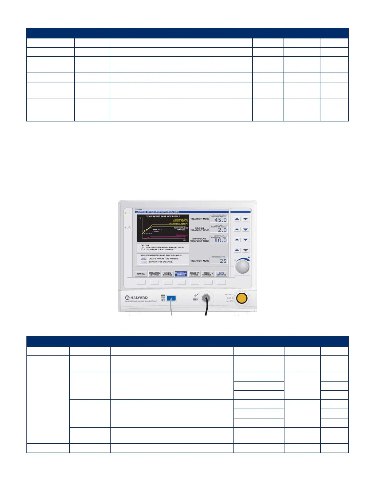
7.7.3 ADVANCED SETTINGS Mode – TRANSDISCAL SETTINGS State
The following screen appears when TRANSDISCAL SETTINGS is selected from the ADVANCED SETTINGS Mode.
• This screen allows adjustment of the warning temperature threshold for the Peripheral Disc Temperature (PDT) by adjusting PERIPHERAL DISC WARNING TEMP.
• The Peripheral Disc Warning Temperature can be used as an aid during treatment. If either PDT A or PDT B exceeds the Peripheral Disc Warning Temperature, the rate of the
Output ON tone increases (the tone is played more often).
• This screen allows adjustment of the RAMP RATE used by the TRANSDISCAL mode to attain the SET TEMPERATURE.
• Settings for two probes are selected with BIPOLAR mode.
• Settings for one probe are selected with MONOPOLAR mode.
• The maximum amount of power available can be adjusted by rotating the dial to change SET POWER LIMIT.
Figure 7-24 ADVANCED SETTINGS Mode – TRANSDISCAL SETTINGS Display
Settings
Aected Mode Parameter DESCRIPTION Range/Units Default Value Increment
Treatment Mode
PERIPHERAL DISC
WARNING TEMP
Set point for the Peripheral Disc Temperature Warning. 30° – 60°C 45°C 0.5°C
BIPOLAR RAMP
RATE
Rate at which temperature increases from the INITIAL TEMP to
the SET TEMP when two probes are used.
0.5° – 5°C/min
2°C/min
0.1°C/min
5° – 10°C/min 5°C/min
10° – 200°C/min 10°C/min
MONOPOLAR RAMP
RATE
Rate at which temperature increases from the INITIAL TEMP to
SET TEMP when one probe is used.
0.5° – 5°C/min
80°C/min
0.1°C/min
5° – 10°C/min 5°C/min
10° – 200°C/min 10°C/min
POST TREATMENT
COOLING
Select to enable or disable the option to go into POST TREATMENT
COOLING after treatment.
ENABLE /DISABLE ENABLE N/A
Treatment Mode POWER LIMIT Maximum power available for temperature control. 1 – 50 W 25 W 1 W
Avanos Exhibit 2069 Page 27
Medtronic, Inc. v. Avanos Medical Sales, LLC
Case IPR2020-0089