8
4.2 Mains Power Cord
• The Generator is shipped with an approved hospital-grade mains power cord.
• Do not use extension cords or three-prong to two-prong adapters. The mains power cord assembly should be periodically checked for damaged insulation or connectors.
4.3 Generator Cleaning and Disinfection Instructions
• Use a mild detergent and damp cloth to clean the Generator cover, front panel, and power cable. The Generator cannot be sterilized. Do not allow uids to enter the chassis.
The Generator may be disinfected using a standard hospital alcohol solution applied with a cloth.
• Do not spray or pour liquids directly on the Generator.
• Non-ammable agents should be used for cleaning and disinfection wherever possible.
• Flammable agents used for cleaning or disinfecting, or as solvents of adhesives, should be allowed to evaporate before the application of high frequency surgery.
4.4 When you get a new Generator
• When you open a box, you will nd:
• Generator
• Power Cord
• User’s Manual
4.5 Generator Maintenance Schedule
• The Generator veries calibration integrity during the Power-On-Self-Test (POST); maintenance is not required.
• For Cleaning and Disinfection Instructions, refer to 4.3 Generator Cleaning and Disinfection Instructions.
4.6 Compatible Accessories
• The HALYARD* COOLIEF* Pain Management Generator has been approved for use with all HALYARD*, K
IMBERLY-CLARK® and Baylis accessories, transducers, and cables. This
includes the PMX, PMP, PMC, PMF, TDX, TDP, TDI, TDA, CRX, and CRP line of products.
5 User Interface Overview
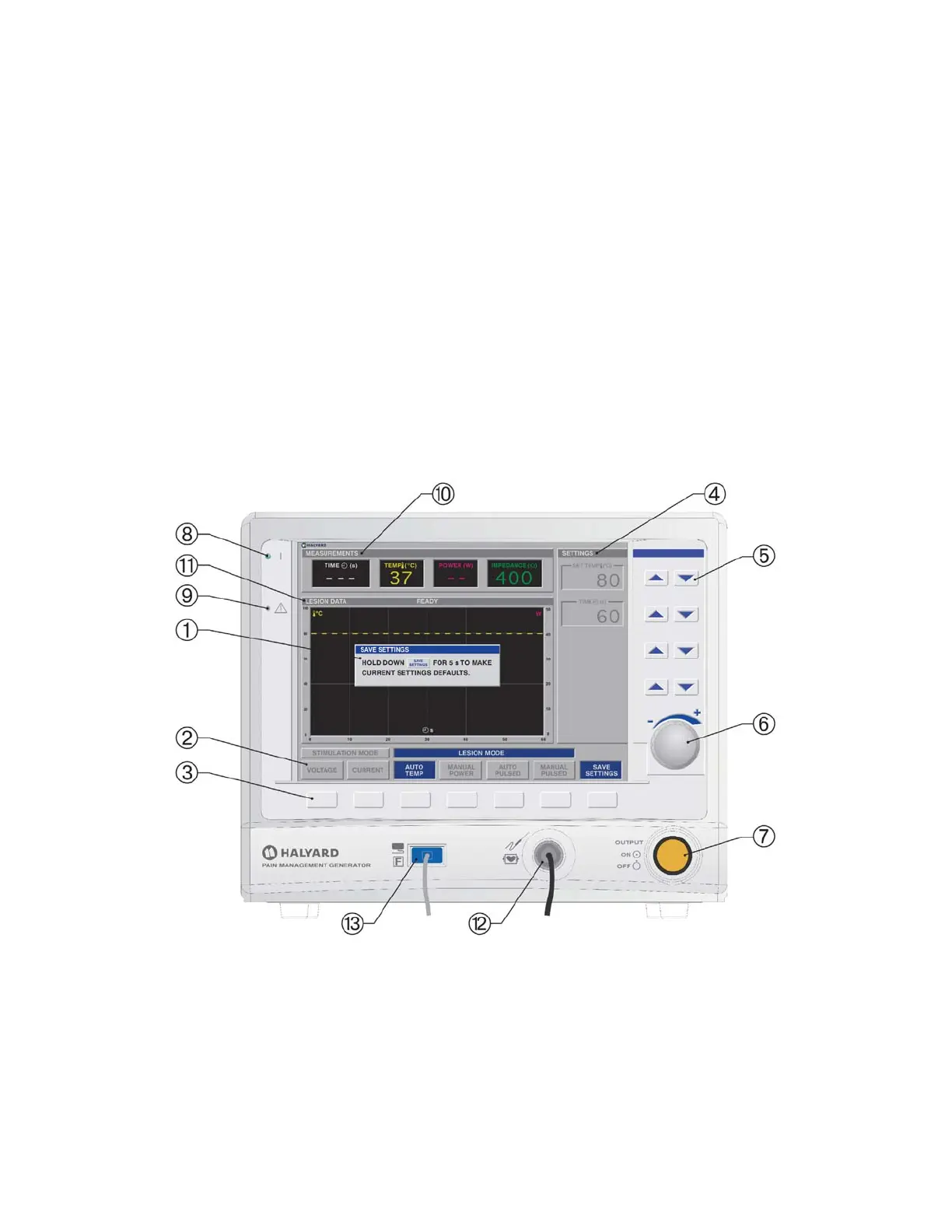
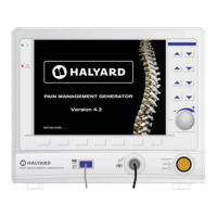
Figure 5-1 Generator front panel
5.1 Front Panel Displays, Controls, and Connections
• Descriptions of front panel features and their functions are given below. Please refer to Figure 5-1 for location of each item on the front panel.
1. Status Window: This window is used to display messages (e.g., Error, Fault, Save Settings).
2. Mode Function Labels: These “labels” are part of the at panel display and indicate the function of the associated Mode Function Key
. Labels highlight to
indicate the current operating mode. If no label is present, the associated button is not used in the present mode.
3. Mode Function Keys: These keys select and change the state of operation. For HALYARD* Pain Management Thermocouple RF probes, STIMULATION or LESION
states are selected with a single press. In RFA mode, PLACEMENT or TREATMENT states are selected with a single press. In COOLED RF mode, STIMULATION or AUTO
TEMP states are selected with a single press. In TRANSDISCAL mode, STIMULATION, PLACEMENT, or TREATMENT states are selected with a single press. The functions of
these keys may vary between modes. The Mode Function Label
above a key always describes the key function.
4. SETTINGS Window: For each state (e.g., VOLTAGE STIMULATION, AUTO TEMP LESION, TRANSDISCAL TREATMENT, etc.), the adjustable settings are shown in the
SETTINGS Window. Up to 5 SETTINGS are adjustable in each state, by using the Setting Adjustment Keys
and Rotary Encoder , to the right of the window.
Avanos Exhibit 2069 Page 8
Medtronic, Inc. v. Avanos Medical Sales, LLC
Case IPR2020-0089


 To Next Page