15
!
"
$
%
&
(
)
/
BP
BR
BM
BN
CN
CM
BQ
BL
BO
BU
BT
CL
CL
#
BS
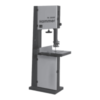
Bandsaw
N3700 e-classic / N3800 / N4400
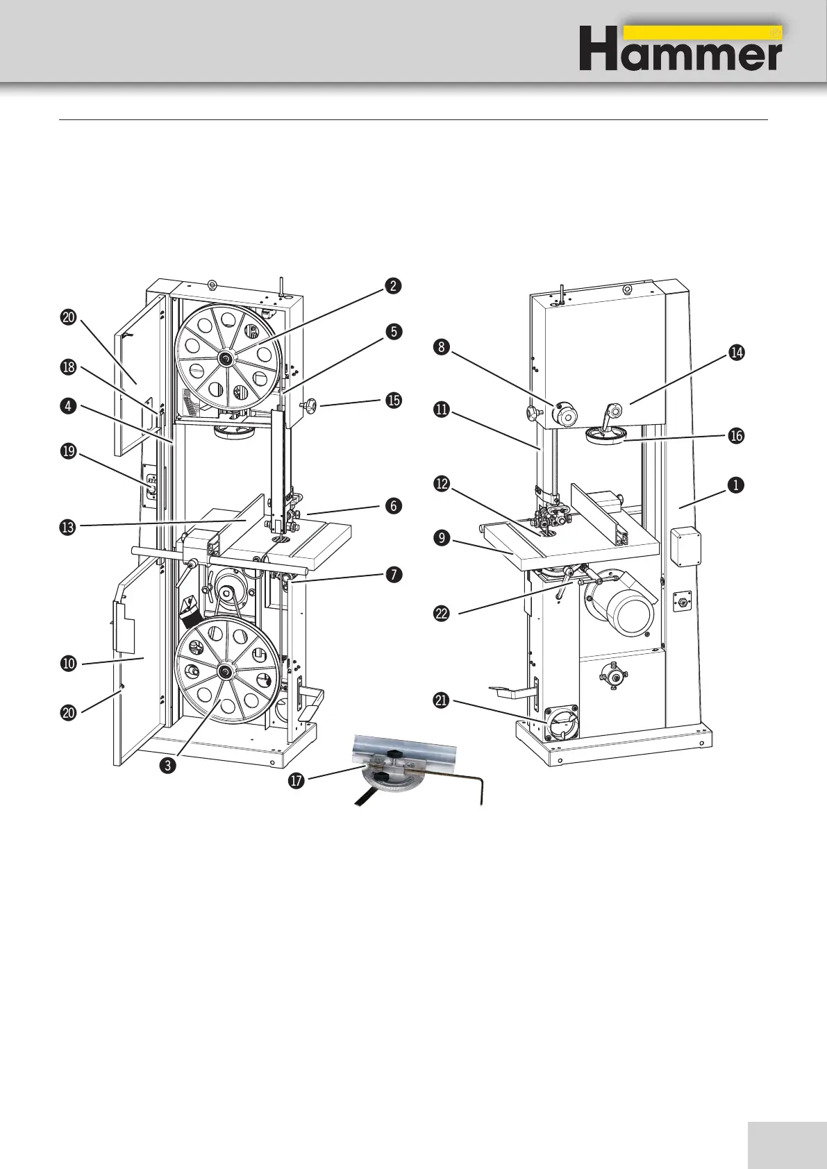
5. Assembly
5.1 Overview
Fig.. 5-1: Overview
Assembly
BO Guide fence
BPSaw blade track - Adjuster hand wheel and clamping
lever
BQLock wheel - Blade guide height adjustment
BRBlade tension hand wheel
BSmitre fence (Accessories)
BTSaw blade tension indicator window
BUOn/Off switch
CLLock wheel - Wheel door
CMVacuum connector
CNTiltable table
(Adjuster hand wheel and clamping lever)
! Machine base-frame
" Upper wheel
# Lower wheel
$ Rising part of saw blade
% Falling part of saw blade
& Upper blade guide
/ Lower blade guide (Optional)
* Blade guide height adjustment
) Work bench
BL Wheel door
BM Height adjustable protection device
BN Table insert