ELEKTRA 2500 HAMTRONIX
6
DETERMINING COR LOGIC
Locate the COS/COR signal on your receiver. This line has a DC voltage that changes when a signal is being received.
If the COR line is 0 volts and goes to a positive voltage when a signal is received it is said to be (positive logic) or
active HIGH. If the COR line is a positive voltage and goes to 0 volts when a signal is received it is said to be
(negative logic) or active LOW. Any voltage under 0.8V is considered low state and greater than 2V high state. If
you receiver has positive COR, jumper J3 (or J4 in case auxiliary port) should be at center and + position. If you
receiver has negative COR, jumper J3 (or J4 in case auxiliary port) should be at center and - position. It is not
necessary to use the input COR1 if using the controller 's internal squelch.
Note: Finding the COR signal on a receiver, according to some customers, is the biggest obstacle to installation. To
meet this demand, we added a squelch circuit that generates its own COR signal, eliminating the need for a COR
connection from the receiver. But keep in mind that using the receiver's own squelch circuit is the most
recommended, since this circuit has been optimized for the specific characteristics of that product. The controller
squelch needs the discriminator signal to work, but the amplitude and frequency response varies depending on the
brand and model, not allowing it to be as efficient as that of the receiver itself. So, if you can choose which one to
use, always prefer the receiver's COR signal.
VIRTUAL ASSITANT
Elektra 2500 is compatible with Virtual Assistants for Artificial Intelligence (Google
Home, Amazon Eco etc.). This allows you to ask questions through the repeater
and get answers on a multitude of subjects. You can ask for the weather forecast,
ask for general information and even schedule ads for specific times. The
prerequisites for installing this functionality are:
• One virtual assistant device
• Availability of Wi-Fi with Internet at the repeater's operating site
• Internal modifications to the assistant device
• Interfacing circuit
Interfacing Google-Elektra
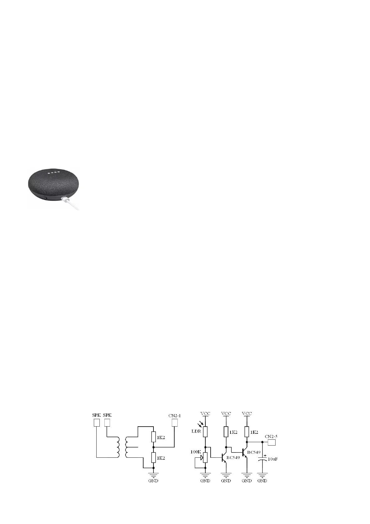
Audio is obtained through the device's internal speaker. In that case, you will need to open it to access the terminals.
Search YouTube for instructions on how to open your virtual assistant.
As the switching power supply of the assistant is noisy, we recommend the use of an audio isolation transformer,
which feeds the signal to the auxiliary port input (CN2-1).
For voice commands, we use the auxiliary port output (CN2-3). As the assistant's microphones are shielded modules
with digital outputs, we cannot interface analog audio directly. The solution was to use a headset speaker to play
the audio close to one of the assistant's microphones. The microphones are located at the edges, aligned to the
LEDs.
For the controller to know when to transmit, we use the circuit below to generate COR based on the lighting of the
assistant's LEDs. Set jumper J3 to positive polarity. Set the auxiliary port to link mode (23-3). Adjust the circuit
potentiometer so that the controller RX2 LED lights up according to the assistant's LEDs.
Initial audio adjustment: adjust the assistant's audio to 50% and set the audio trimpot of the RX2 auxiliary port in
12 o´clock. Ask the assistant any questions via repeater and check that the audio level for the assistant's microphone
is enough for him to respond. If it is too low, increase TX2 or even RX1. The settings TX1, RX2 and the assistant
volume itself influences the level of reproduction. Experiment with the two positions of the J2 de-emphasis jumper
for better reproduction audio.
 Loading...