29.06.2016
DOUBLE-SEAT VALVE (Type 491)
BA 049100.06 EN 17 / 34
6.1.3 Cleaning – Balancer (B)
07
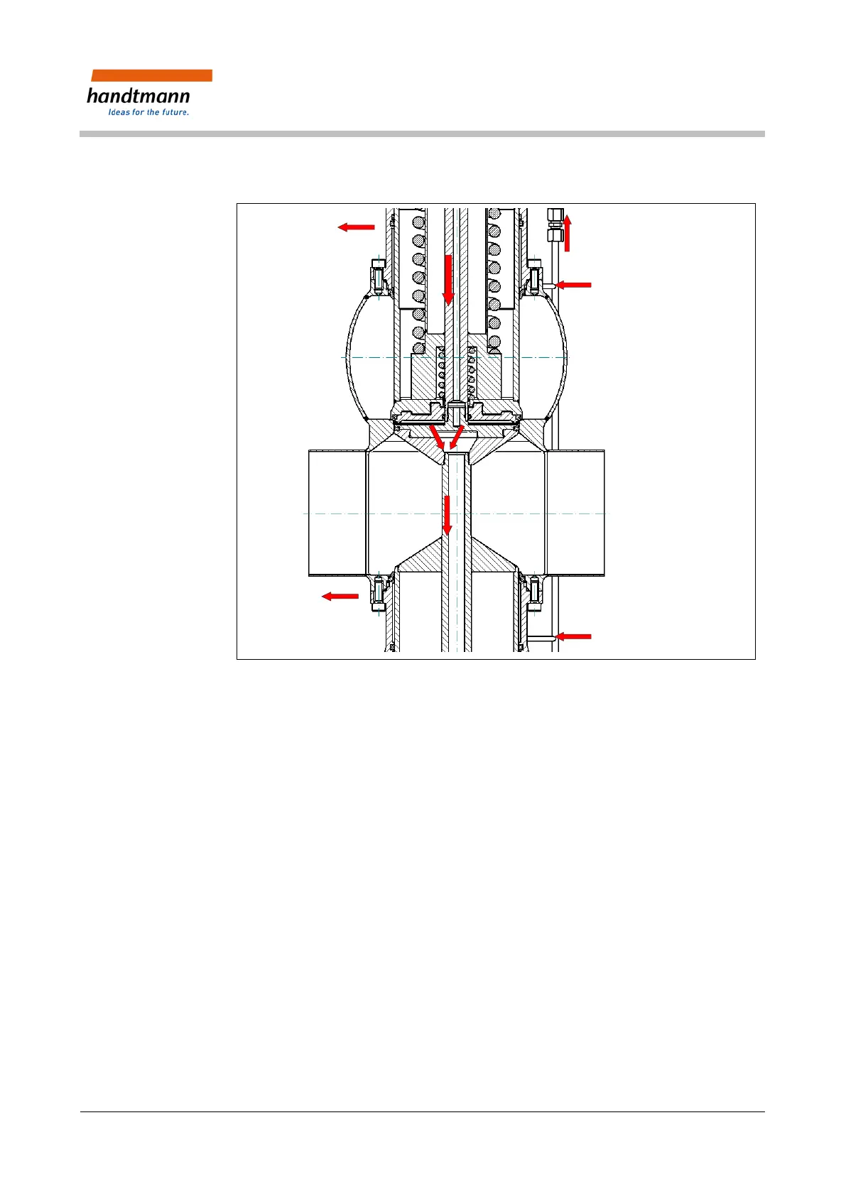
Fig. 5: Cleaning methods
In hygienically sensitive processes we recommend connecting the flushing
chambers to the CIP circuit via controllable valves.
• During the valve switching process the balancers move between the product
chamber and the adjacent upper and lower flushing chambers.
• The cleaning medium flows through the flushing chambers via a stationary
inflow and outflow.
• The balancers’ upper and lower product-affected area are thus integrated
into the cleaning process.
6.1.4 Cleaning – Leakage Chamber (L)
• In the valve’s closed and open position, the leakage chamber between the
two valve disks is sealed all the way to the piping system.
• Through a stationary supply pipe, cleaning medium can be injected from
above into the leakage chamber.
• The cleaning medium is guided outdoors through the leakage outlet.