29.06.2016
DOUBLE-SEAT VALVE (Type 491)
BA 049100.06 EN 21 / 34
8 Disassembly/ Assembly
8.1 Disassembly of the Valve Inset
The disassembly of the valve inset is described in this chapter.
08
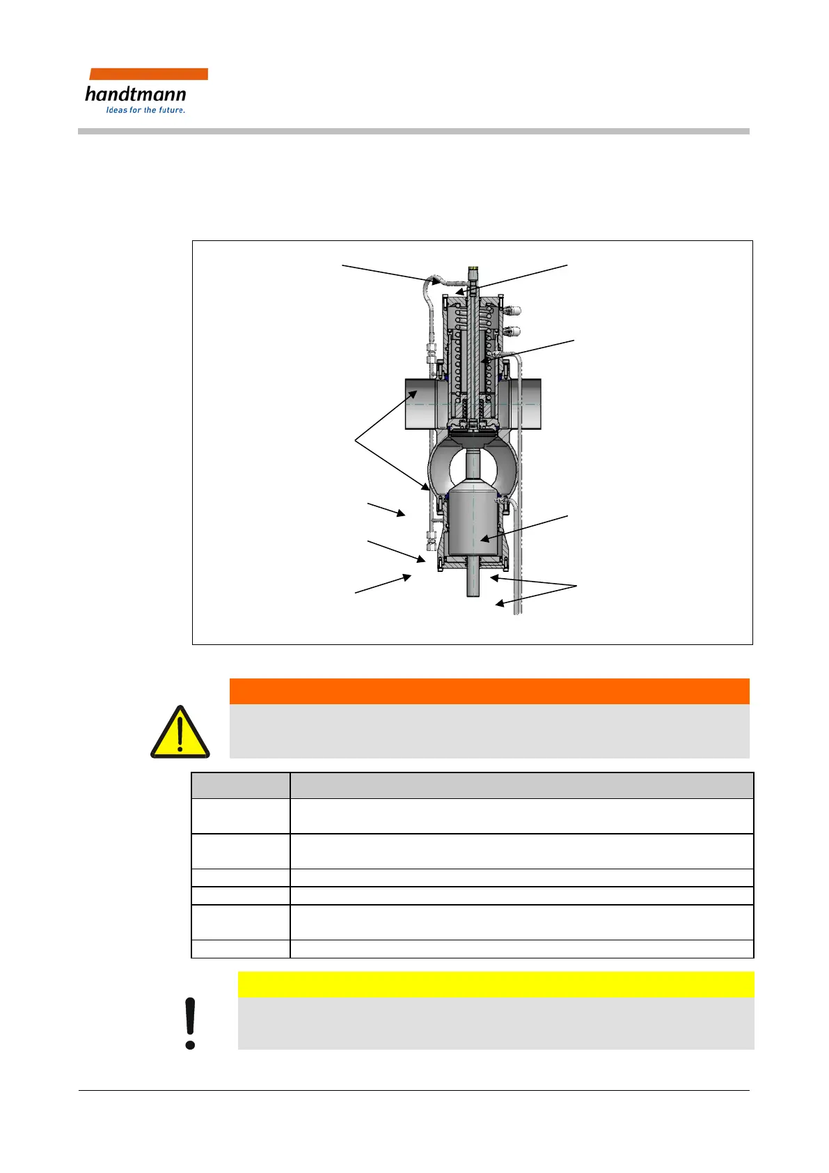
Fig. 7: Representation of the valve inset
Warning - Danger from electrical current!
Before disassembly, the connections for auxiliary energy and the supply pipes (electric,
pneumatic, CIP) should be separated from the valve.
Serial No. Type of activity
Unscrew the banjo bolt with the flushing pipe [2], the flush chamber piping [7]
and the plug for the proximity switch.
Place the assembly device [1] on the valve cover.
Screw the assembly devices threaded rod into the valve rod.
Turn the threaded rod’s lock nut and lift the valve approx. 6 mm.
Remove the securing bolt [4] for the valve inset.
Lift the assembly device with the valve inset [3] completely out of the valve
housing.
Unscrew the lower bushing [5]. (Only necessary when changing the lip sealing).
Caution – Damage to components!
Do not damage the valve disks and balancer!