Installation and Commissioning
20 / 34
DOUBLE-SEAT VALVE (Type 491)
BA 049100.06 EN 29.06.2016
08
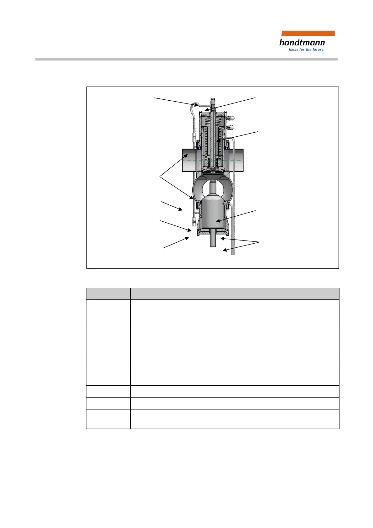
Fig. 6: Representation of the valve inset
Serial No. Type of activity
1 Locate the bushing below [9] with actuator piston [6] and seals (Ch. 10.6) and
screw these together with the valve housing.
Position the bushing after the connection nipple for CIP collecting pipe [8].
2 Locate the complete valve inset [3] tension-free in the valve housing.
Position the valve inset after connection for CIP collecting pipe
[8]. Turn only in a clockwise direction.
3 Screw the valve inset [3] complete with the valve housing.
4 Tighten the collecting pipe [8] and the overflow pipe [7];
if necessary screw on the external CIP supply pipe.
5 Attach the electrical connections to the control unit.
6 Carry out a seal and function check.
7 Direct control through compressed air pipe at the compressed air connection
G1/8" [5] or if available at the control head.