29.06.2016
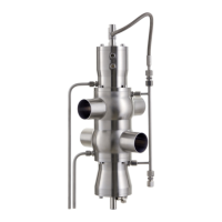
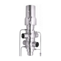
DOUBLE-SEAT VALVE (Type 491)
BA 049100.06 EN 25 / 34
8.5 Valve assembly
The valve inset’s assembly takes place in the reverse order.
The following points must be adhered to:
• Quad rings should be assembled heavily greased.
• When tensioning the springs make sure that the valve rod and the guide
bore-hole in the piston are aligned.
• When assembling, the upper form seal (70) and the lower form seal (80) are
to be placed in grooves.
• O-ring (90) is to be fitted with light lubrication. At the same time, make sure
that the O-ring is not twisted. Press the O-ring evenly into the insertion.
• To insert the upper lip sealing (140), make sure that the lip sealing can be
mounted lightly lubricated on to the valve inset until the seal lies evenly on
the upper bushing’s back-up ring. Mount the O-ring (150), lightly lubricated,
on the upper bushing.
• To install the lower lip sealing (140), make sure that the lightly lubricated lip
seal is placed in the valve housing. Mount the O-ring (150) on the lower
bushing and screw the lower bushing on to the valve housing.
• Install the lifted valve inset in the valve housing and screw tightly.
• Finally, the seal of the lip sealing should be checked.
Note:
After installing the seals, the valve disk should be tightly screwed up to the metallic
stopper.
Note:
The valve seat in the housing must be checked regularly for dirt and damages.