39
Step 1
Completely read the instructions included with your
engine and follow the recommended break-in procedure.
Step 2
At the field, adjust the engine to a slightly rich
setting at full throttle and adjust the idle and low-
speed needle so that a consistent idle is achieved.
Step 3
Before you fly, be sure that your engine idles
reliably, transitions and runs at all throttle
settings. Only when this is achieved should
any plane be considered ready for flight.
The amount of control throw should be adjusted as
closely as possible using mechanical means, rather
than making large changes electronically at the radio.
By moving the position of the clevis at the control
horn toward the outermost hole, you will decrease
the amount of control throw of the control surface.
Moving it toward the control surface will increase the
amount of throw. Moving the pushrod wire at the servo
arm will have the opposite effect: Moving it closer to
center will decrease throw, and away from center will
increase throw. Work with a combination of the two to
achieve the closest or exact control throws listed.
Aileron 9/16" (14mm) up 9/16" (14mm) down
Note: Aileron throw is measured at the
inboard trailing edge of the aileron.
Elevator 7/16" (11mm) up 1/2" (13mm) down
Note: Elevator throw is measured at the
inboard trailing edge of the elevator.
Rudder 1" (25mm) right 1" (25mm) left
Note: Rudder throw is measured
at the bottom of the rudder.
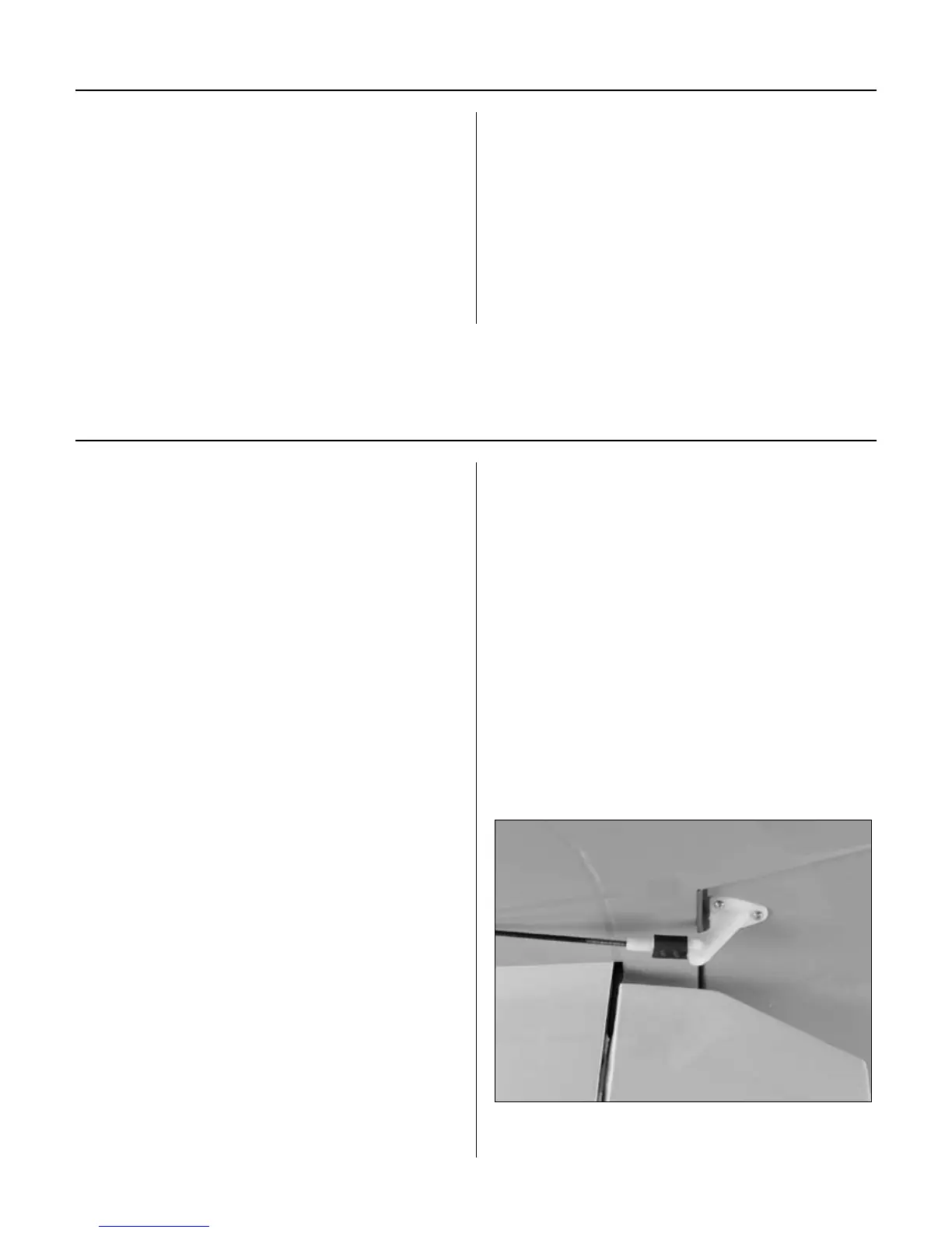
Once the control throws have been set, use the
supplied heat shrink tubing on each clevis to
prevent them from opening during flight.
Adjusting the Engine
Control Throws