35
Required Parts
• Nylon clevis (2) • Nylon wire keeper (2)
• Nylon control horn (3) • 2-56 x 1/2" screw (6)
• Fuselage assembly • Servo w/hardware (3)
• Quick connector • Receiver
• Quick connector backplate • Receiver battery
• Pushrod wire (29
3
/
4
") (756mm) (2)
• 3mm setcrews • 1/4" (6mm) foam
• Switch harness
Required Tools and Adhesives
• 6-minute epoxy • Thin CA
• Felt-tipped pen • Hobby knife
• Ruler • Drill
• Drill bit: 1/16" (1.5mm), 5/64" (2mm),
3/32" (2.5mm)
• Phillips screwdriver (small)
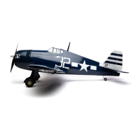
Step 1
Wrap the receiver and receiver battery in foam.
Secure them to the radio tray using rubber
bands or hook and loop straps. Install the servo
hardware and install the servos into the servo
tray. Connect the servos to the receiver and the
extensions for the aileron and retract servos.
Note: The receiver battery is located
under the servo tray. The tray shows
the four-stroke throttle servo location.
The empty opening is the servo location
for the two-stroke throttle servo.
Important: Apply 2–3 drops of thin
CA onto each servo screw to prevent
them from vibrating loose in flight.
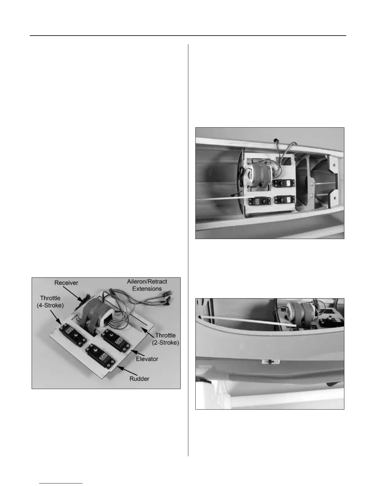
Step 2
Use 6-minute epoxy to glue the servo tray inside
the fuselage. Make sure there is a good bond
between the formers and servo tray to prevent it
from coming loose during the life of the aircraft.
Step 3
Install a switch harness opposite the side of
the engine exhaust. Route the antenna through
the bottom of the fuselage and secure it to a
location at the tail with rubber bands.
Section 10: Radio Installation