EasyManua.ls Logo

HANKISON PR700 User Manual

Default Icon
20 pages
To Next Page IconTo Next Page
Page #1 background imageLoading...
Page #1 background image
1
7610.483.4B 8/01
INSTRUCTION MANUAL
Contents
GENERAL SAFETY INFORMATION ................................. 2
RECEIVING, MOVING, UNPACKING ............................... 2
1.0 INSTALLATION ........................................................ 3
2.0 OPERATION ........................................................... 6
3.0 MAINTENANCE ...................................................... 8
SIZING ........................................................................... 9
ENGINEERING DATA ..............................................10, 11
ELECTRICAL SCHEMATICS ......................................12, 13
CONTROL TRANSFORMER CONNECTIONS.................. 14
DIMENSIONS / WEIGHTS ............................................. 15
TROUBLESHOOTING .................................................... 16
PARTS LIST .............................................................17, 18
WARRANTY................................................................. 20
Models: PR500, PR600, PR700, PR800,
PR1000, PR1200, PR1600,
PR2000, and PR2300
SERVICE DEPARTMENT: (724) 746-1100
REFRIGERATED
TYPE
COMPRESSED
AIR DRYERS
®
IMPORTANT - 380-420V/3ph/50Hz models - control
transformer is wired to operate on a voltage range of 391
to 418. For voltages outside this range rewire transformer
as shown on page 12.
M
M
Question and Answer IconNeed help?

Do you have a question about the HANKISON PR700 and is the answer not in the manual?

HANKISON PR700 Specifications

General IconGeneral
BrandHANKISON
ModelPR700
CategoryDehumidifier
LanguageEnglish

Summary

General Safety Information

Pressurized Devices Safety

Safety precautions for equipment operating under pressure.

Electrical Safety Precautions

Guidelines for safe electrical connections and maintenance.

Installation Procedures

Location Selection

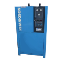
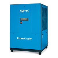
Guidance on selecting an appropriate installation location for the dryer.

Piping and Electrical Connections

Operation and Control

Minimum/Maximum Operating Conditions

Specifies the acceptable operating ranges for pressure and temperature.

Start-up Procedures

Step-by-step guide for safely starting the dryer.

Maintenance Guidelines

Sizing and Capacity Calculation

Determining Dryer Capacity

How to calculate maximum inlet flow capacity using correction factors.

Pressure Drop Calculation

Method for determining pressure drop at increased flow rates.

Rated Capacity and Pressure Data

Table showing rated capacity and pressure drop at standard conditions.

Air Capacity Correction Factors

Table of multipliers for inlet air conditions affecting capacity.

Electrical Connections and Wiring Diagrams

Wiring Diagram - Standard Control Panel

Schematic showing electrical layout for standard control panels.

Digital Control Panel Wiring Diagram

Digital Control Panel Schematic

Schematic for the digital control panel wiring.

Troubleshooting Guide

Water Downstream of Dryer

Troubleshooting steps for residual moisture in downstream pipelines.

High Pressure Drop

Diagnosing and resolving high pressure drop issues across the dryer.

High Temperature Alarm

Steps to address high air outlet temperature alarms.

Refrigeration System Malfunctions

Troubleshooting power, pressure, and compressor issues.

Warranty Information

Manufacturer's Warranty Terms

Details of the product warranty coverage and period.

Warranty Service Authorization

Requirement for service department authorization before repairs.

Related product manuals