3
NOTE: Outdoor installation: Standard dryers are designed
for indoor installation. Contact manufacturer if installing
outdoors.
1.0 INST ALLATION
1.1 Location
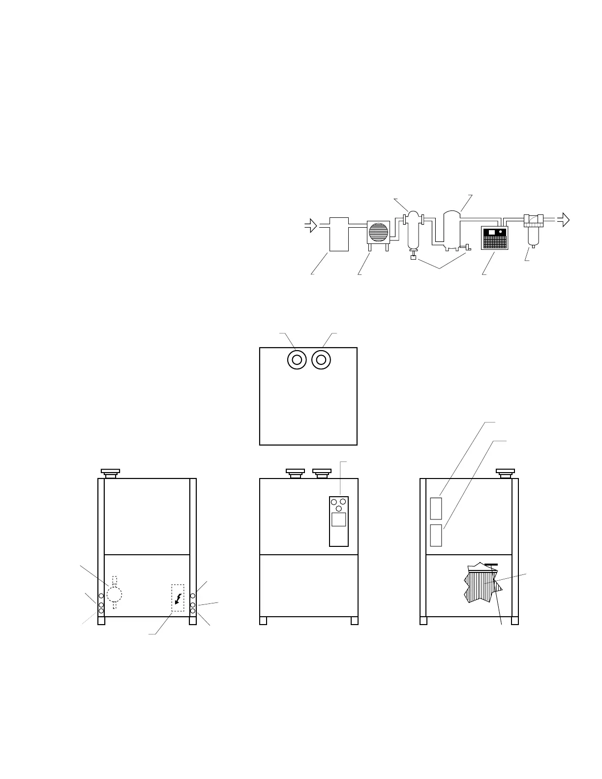
A. For typical placement in a compressed air system, see
drawing at right.
B. Air compressor intake - Locate air compressor so that
contaminants potentially harmful to the dryer (e.g.
ammonia) are not drawn into the air system.
C. Air-cooled units - Free air flow - Ambient air should be
free to flow across the refrigeration condenser. Do not
block either side of the cabinet. Leave at least 36 inches
(915 mm) clearance for free air flow.
COMPRESSOR
AFTERCOOLER
SEPARATOR
RECEIVER
TANK
DRYER
OIL
REMOVAL
FILTER
AUTOMATIC
DRAINS
1.2 Mounting
A. Mount dryer on firm level surface.
B. Dryers are furnished with removable shipping pads.
Remove prior to installation if desired. Dryers may be
bolted to the floor if desired.
IMPORTANT - Read prior to starting this equiptment.
LEFT SIDE VIEW
FRONT VIEW RIGHT SIDE VIEW
AIR OUT AIR IN
DRAIN
ASSY.
(2)
MANUAL
DRAIN
AUTOMATIC
DRAIN
ELECTRICAL
ENCLOSURE
ELECTRICAL
ENTRY
MANUAL
DRAIN
AUTOMATIC
DRAIN
CONTROL PANEL
SERIAL TAG
INSTRUCTION TAG
CONDENSER
BLOW OFF GUN
FOR CONDENSER CLEANING