39
GB 08 04
Operation
FF
FF
F
ilterilter
ilterilter
ilter
ss
ss
s
All filters should always be used, and their function
checked regularly. The mesh size of the filter in use
should always be smaller than the flow average of the
nozzles used. Therefore, pay attention to the correct
combination of filters, mesh size.
Self-cSelf-c
Self-cSelf-c
Self-c
leaning fleaning f
leaning fleaning f
leaning f
ilterilter
ilterilter
ilter
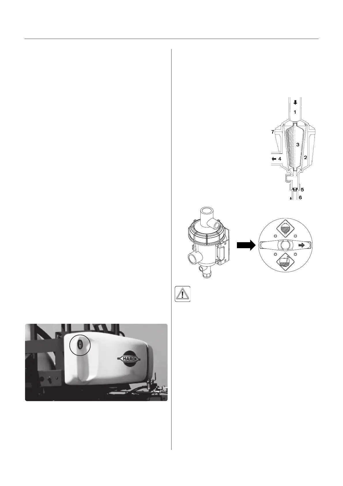
Operating diagram
1. From pump
2. Double filter screen
3. Guide cone
4. To operating unit
5. Replaceable restrictor
6. Return to tank
7. Screw-joint
The self-cleaning filter is operated
via the yellow MANIFOLD valve.
IMPORTANT! The yellow MANIFOLD valve
should normally be open, but must be closed in
the following cases:
1. If rinsing with water from the rinsing tank and a
quantity of spray liquid still remains in the main tank
(otherwise the spray liquid will be diluted).
2. If opening the self-cleaning filter and a quantity of
spray liquid still remains in the main tank (otherwise
there is a risk that spray liquid will flow out).
Choice of correct restrictor
It is important to have a large flow through the filter. This
is achieved by choosing the restrictor size in relation to
the liquid consumption of the spray boom.
4 restrictors are supplied. Use the green one (largest
orifice) first.
NOTE! HEREAFTER ADJUSTMENT OF PRESSURE
EQUALISATION WILL ONLY BE NEEDED WHEN:
1. YOU CHANGE TO NOZZLES WITH OTHER CA-
PACITIES
2. THE NOZZLE OUTPUT INCREASES AS THE NOZ-
ZLES WEAR
OperOper
OperOper
Oper
aa
aa
a
ting the contrting the contr
ting the contrting the contr
ting the contr
ol unit while sprol unit while spr
ol unit while sprol unit while spr
ol unit while spr
aa
aa
a
yingying
yingying
ying
In order to close the entire boom, switch ON/OFF A to
off position. This returns the pump output to the tank
through the return system.
The diaphragm Non-drip valves ensure instantaneous
closing of all nozzles.
In order to close one or more sections of the boom,
switch the relevant distribution valve V to off position.
The pressure equalisation ensures that the pressure
does not rise in the sections which are to remain open.
When the sprayer is put aside, the control box and the
multi plug must be protected against moisture and dirt.
A plastic bag may be used to protect the multi plug.
RR
RR
R
emote premote pr
emote premote pr
emote pr
essuressur
essuressur
essur
e ge g
e ge g
e g
augaug
augaug
aug
e (ife (if
e (ife (if
e (if
f f
f f
f
itted)itted)
itted)itted)
itted)
The remote pressure gauge is integrated in the front
locker. This gauge measures the working pressure in the
boom tubes as close to the nozzles as possible. This
pressure reading will always be slightly lower than the
reading at the operating unit pressure gauge.
The outputs stated in the nozzle charts are always based
on the pressure measured at the nozzle.
Always adjust pressure when calibrating and spraying
according to readings at the Remote pressure gauge.
(If no front locker is fitted to the trailer the pressure
gauge is situated at the platform instead).
T059-0001
T060-0118
T026-0096
 Loading...