5
HARDI
®
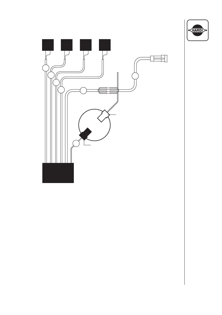
FOAM MARKER STANDARD VERSION
Foam Marker Wiring Schematic
Fig. 2
A
B
C
D
E
G
F
LEFT
AIR
VALVE
RIGHT
AIR
VALVE
LEFT
SOLUTION
VALVE
RIGHT
SOLUTION
VALVE
RED WIRE
(NOT USED)
ORANGE
WIRE
COMPRESSOR
MOTOR
WHITE
TERMINAL
BLACK
TERMINAL
A. Brown & Gray Pair w/Brown Tie (To Left Air Valve)
B. Violet & Gray Pair w/Red Tie (To Left Solution Valve)
C. White & Gray Pair w/Green Tie (To Right Solution Valve)
D. Black & Gray Pair w/Yellow Tie (To Right Air Valve)
E. Wire Bundle w/Blue Tie (To 26004103 Cable)
F. 26004103 Cable (Orange wire to White Terminal
of Compressor Motor, Red wire not used, All other
wires to same colored wires of Wire Bundle E)
G. Single Blue Wire (To Black Terminal of Compressor Motor)
STANDARD FOAMER
MODULE 26004003
26004103
CABLE
NOTE: Extension cable #26001903 is re-
quired on New Navigator Sprayers
to connect the compressor box to
the power supply cable.
 Loading...