Do you have a question about the Harman Kardon 930 and is the answer not in the manual?
Outlines the warranty coverage for material and workmanship defects for two years from purchase.
Specifies items not covered by the warranty, such as wooden enclosure damage and shipping costs.
Mandates retaining the original bill of sale for warranty service claims.
Provides contact information for customer service and authorized repair assistance.
Specifies minimum clearances for proper airflow around the receiver.
Details AC power connection, voltage compatibility, and auxiliary outlets.
Explains the role of fuses and the importance of using correct replacements.
Guides on connecting speakers for correct phase alignment and optimal sound.
Instructions for connecting four speakers across two independent systems.
Diagrams for connecting speakers in stereo and monophonic modes with loading resistors.
How to connect 300-ohm twin lead or 75-ohm coaxial FM antennas.
Instructions for connecting the AM loopstick or an external wire antenna.
Using preamplifier output and power amplifier input connections for external processors.
Connecting magnetic pickup turntables to the dedicated Phono 1 and Phono 2 inputs.
Establishing a common ground between the receiver and other audio components.
Connecting high-level sources like tape decks, tuners, or crystal pickups.
Connecting tape recorders for recording and monitoring programs.
Selecting between stereo, monophonic, and channel reverse operation.
Adjusting the overall signal level for playback.
Fine-tuning the sound level between left and right channels.
Adjusting low and high frequencies for desired tonal balance.
Selecting the input source for playback (Phono, AM, FM, Aux).
Turning the receiver on and off, and controlling switched outlets.
Selecting which speaker system(s) are active.
Enabling tape monitoring for recording and playback comparison.
Reducing high-frequency noise like scratch and hiss.
Reducing low-frequency noise such as record rumble.
Bypassing tone controls for a flat frequency response.
Enhancing low-frequency response at low listening levels.
Disabling FM muting to hear weaker stations or reduce interstation noise.
Reducing noise associated with weak FM multiplex signals.
Automatically selecting stereo FM broadcasts or forcing mono.
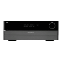
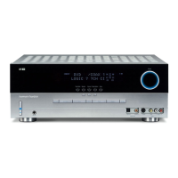
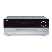
The Harman-Kardon Model 930 is a solid-state receiver designed for high-fidelity audio reproduction, integrating AM/FM/Stereo FM tuning with amplification capabilities. This receiver represents a new era in audio design, emphasizing clean, transparent sound and robust performance.
The core function of the Model 930 is to receive radio broadcasts (AM, FM, and Stereo FM) and amplify audio signals from various external sources, delivering them to speakers or headphones. It features a comprehensive set of controls and inputs to manage different audio sources and tailor the sound to the listener's preference and room acoustics.
The receiver includes a built-in AM/FM/Stereo FM tuner. For FM reception, it can utilize either a 300-ohm balanced twin lead or a 75-ohm unbalanced co-axial cable. A simple 48-inch wire is often sufficient for most locations, but an external antenna can be connected for improved reception in more remote or challenging areas. The AM section is equipped with a loopstick antenna on the rear, suitable for normal signal areas, with provisions for an additional outdoor antenna for extended range and noise reduction.
The amplification section is designed with two separate power supplies, one for each channel. This unique design ensures flawless performance by preventing one channel's power demands from affecting the other, resulting in cleaner and more transparent sound delivery, especially at full RMS power output. The receiver is also a proud heir to the HARMAN-KARDON trademark of ultra-wideband frequency response, which aims to reproduce sound beyond the limits of human hearing, adding extra realism to the audible range.
Input flexibility is a key feature, with multiple options for connecting audio sources. Two sets of PHONO receptacles are provided for magnetic pickups, each with RIAA equalization, allowing simultaneous connection of a record changer and a manual turntable. Two pairs of AUX INPUT receptacles accommodate high-level sources such as ceramic or crystal pickups, reel-to-reel tape recorders, cassette tape recorders, TVs, or a second stereo tuner. Additionally, two pairs of TAPE MONITOR receptacles (TAPE MONITOR 1 and TAPE MONITOR 2) allow for monitoring recordings as they are being made, particularly useful for professional tape recorders with separate record and playback heads.
The receiver also includes PREAMP OUT and MAIN AMP IN receptacles. These are designed for integrating external equipment like electronic audio equalizers, reverberation units, or quadraphonic processors between the preamplifier and power amplifier stages. When no such accessories are used, patch cords must be installed between these receptacles for the receiver to function.
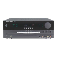
The front panel of the Model 930 is equipped with a variety of controls and indicators for intuitive operation. The FUNCTION switch allows selection between PHONO 1, PHONO 2, AM, FM, AUX 1, and AUX 2 sources. Illuminated indicator lights behind the dial glass visually confirm the selected function.
Tuning for radio stations is facilitated by a TUNING KNOB and two D'Arsonval movement tuning meters: an FM BALANCE METER and a SIGNAL STRENGTH METER. The FM balance meter operates on a null or "zero" center principle, guiding the user to the point of minimum distortion and optimum FM reception. The signal strength meter indicates the level of the incoming signal. For AM tuning, only the signal strength meter is used. The dial scale features FM frequency (88-108 MHz), AM frequency, and a logging scale (0-100) for easily recalling favorite stations. A STEREO INDICATOR light illuminates when an FM stereo program is being received.
Sound shaping is handled by BASS and TREBLE controls, which can be adjusted for both channels simultaneously or individually. The outer knob adjusts the LEFT channel, and the inner knob adjusts the RIGHT channel. The BALANCE control allows fine-tuning of the sound distribution between the left and right speakers. The VOLUME control adjusts the overall signal level, with a two-section design ensuring identical volume levels for both channels.
Several push/push type switches offer additional control over audio processing:
A STEREO HEADPHONE RECEPTACLE on the front panel allows private listening with any impedance headphones, always active.
The Model 930 is designed for reliability, but some considerations are important for its longevity and proper function.
Ventilation: Although the receiver rarely generates excessive heat, adequate ventilation is recommended. Leaving the back of the cabinet open, or providing large holes/slots at the bottom and top of the cabinet, ensures proper airflow. A minimum clearance of two inches on the sides and rear, and three inches above, is advised. Accessories should not obstruct ventilation.
Fusing: The receiver incorporates three fuses for protection against overload, short circuits, and excess current. An AC fuse (3A-3AG) protects the entire system, while two speaker fuses (also 3A-3AG) protect the output stages. In the event of a fuse failure, it is crucial to replace it ONLY with the same type and rating to avoid severe damage and maintain warranty coverage.
Speaker Connections: Careful attention to speaker wiring is essential. Avoid accidental shorts, as repetitive shorting can damage transistors. The receiver is compatible with speakers having impedances of 4, 8, or 16 ohms. When using multiple speaker systems, ensure the total load impedance does not fall below 4 ohms to prevent blowing the speaker fuses.
Ground Connection: A GND terminal on the rear panel allows for establishing a common "ground" between the receiver and other associated equipment, which can help eliminate hum in the audio system. If hum is experienced, troubleshooting steps include reversing AC line cords and connecting a single lead from the record player chassis to the ground post.
Power Outlets: Two auxiliary AC power outlets are provided on the rear panel. One is "always alive," and the other is "switched," meaning it is live only when the receiver's power switch is ON. This allows for convenient control of accessory equipment like tape recorders or record players.
Service and Warranty: The unit is covered by a two-year warranty against defects in material and workmanship under normal use. For service, it is necessary to retain the original bill of sale. The manufacturer emphasizes that the unit should NOT be shipped for service without prior authorization and a proper authorization form. The internal components are not user-serviceable, and the cover should only be removed by qualified personnel.
| Power Output | 45 watts per channel into 8Ω (stereo) |
|---|---|
| Frequency Response | 20Hz to 20kHz |
| Tuning Range | FM, MW |
| Damping Factor | 40 |
| Input Sensitivity | 2.5mV (MM) |
| Signal to Noise Ratio | 75dB |