➁ Pin Functions
Pin Number
Designator I/O Functions
1 AVDD3 I Analog Positive Power Source Pin
2 FPDIN I Laser Monitor Diode Contact Pin
3 FVREF I Reference Voltage Level Input Pin for APC
4 FPDO I/O Laser Monitor Output (Connect I/V conversion resistor between
FPDIN)/Laser Monitor Voltage Input
5 WREF I Power Setting Voltage Input for Write APC
6 VWDC O Laser Driver Control Output for Write
7 VWDCN I Laser Driver Control Amp (-) Pin for Write
8 MPP O Main Push-Pull Signal Output
9 TEIN I Input for Tracking Signal Processor
10 TE O Tracking Error Signal Output
11 FE O Focus Error Signal Output
12 BIAS O Bias Resistance Contact Pin. RBIAS=4.7kΩ
13 AGND1 O Decoupling Pin for Internal Reference Voltage
14 VREF I/O
Decoupling Pin for Internal Reference Voltage/Reference Voltage Input Pin
15 NC(VSS) -
16 XLAT I Latch Input for Register Settings
17 SDATA I Data Input for Register Settings
18 SCLK I Clock Input for Register Settings
19 MCLK I Main Clock Input (34.5744 MHz)
20 DVSS I Digital Ground Pin
21 DVDD I Digital Positive Power Source Pin
22 ATFG O ATIP FG Output (Wobble
Signal
after binary Operation)
23 XTOR O Tracking Amplitude Detection Output
24 XTAND O Off-Track Detection Output
25 TZC O Tracking Zero-Cross Detection Signal Output
26 RECD2 O
Recording Area Detection Signal 2. "H" Recorded Section, "L" Unrecorded
Section
27 RECD1 O
Recording Area Detection Signal 1. "H" Recorded section, "L" Unrecorded
Section
28 RZC O RF Zero-Cross Detection Signal Output
29 DECEFM O EFM Output after Slice (reverse)
30 XDECEFM O EFM Output after Slice (normal rotation)
31 GAINUP3 I 0, +18dB Switch Control Input Pin. "H" +18dB, "L" 0dB
32 GAINUP2 I 0, +18dB Switch Control Input Pin. "H" +18dB, "L" 0dB
33 GAINUP1 I 0, +18dB Switch Control Input Pin. "H" +18dB, "L" 0dB
34 SLHOLD I Slice Level Hold Signal Input Pin. "H" Hold
35 MPDSH I Sample Pulse Input for Main Beam Signal. "H" Sample, "L" Hold
36 SPDSH I Sample Pulse Input for Side Beam Signal. "H" Sample, "L" Hold
37 WBLSH I Sample Pulse Input for Wobble Signal. "H" Sample, "L" Hold
38 RFPDSH I Sample Pulse Input for Read APC. "H" Sample, "L" Hold
39 WFPDSH I Sainple Pulse Input for Write APC. "H" Sample, "L" Hold
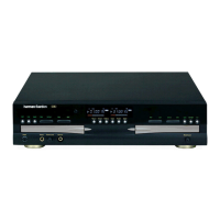
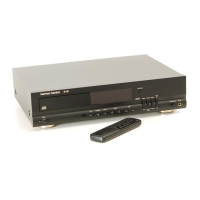
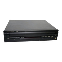
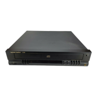
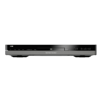
CDR2 harman/kardon