MCLK—Audio Master Clock: Pin 44
Bidirectional master audio clock. MCLK can be an output from the CS493XX that provides an
oversampled audio-output clock at either 128 Fs, 256 Fs, or 512 Fs. MCLK can be an input at
128 Fs, 256 Fs, 384 Fs, or 512 Fs. MCLK is used to derive SCLK and LRCLK when SCLK
and LRCLK are driven by the CS493XX. BIDIRE CT IONAL - Default: INPUT
SCLK—Audio Output Bit Clock: Pin 43
Bidirectional digital-audio output bit clock. SCLK can be an output that is derived from MCLK
to provide 32 Fs, 64 Fs, 128 Fs, 256 Fs, or 512 Fs, depending on the MCLK rate and the
digital-output configuration. SCLK can also be an input and must be at least 48Fs or greater.
As an input, SCLK is independent of MCLK. BIDIRECTI ONAL - D e faul t: INPUT
LRCLK—Audio Output Sample Rate Clock: Pin 42
Bidirectional digital-audio output-sample-rate clock. LRCLK can be an output that is divided
from MCLK to provide the output sample rate depending on the output configuration. LRCLK
can also be an input. As an input LRCLK is independent of MCLK.
BIDIREC TIONAL - De fault: INPUT
AUDATA3,XMT958—SPDIF Transmitter Output, Digital Audio Output 3: Pin 3
CMOS level output that contains a biphase-encoded clock for synchronously providing two
channels of PCM digital audio or a IEC61937 compressed-data interface or both. This output
typically connects to the input of an RS-422 transmitter or to the input of an optical transmitter.
Conversely this pin can be configured to be a third digital audio output. OUTPUT
SCLKN1, STCCLK2—PCM Audio Input Bit Clock: Pin 25
Bidirectional digital-audio bit clock that is an output in master mode and an input in slave
mode. In slave mode, SCLKN1 operates asynchronously from all other CS493XX clocks. In
master mode, SCLKN1 is derived from the CS493XX internal clock generator. In either master
or slave mode, the active edge of SCLKN1 can be programmed by the DSP. For applications
supporting PES layer synchronization this pin can be used as STCCLK2, which provides a path
to the internal STC 33 bit counter. BIDIRECTIO NAL - De fault: I NPUT
LRCLKN1—PCM Audio Input Sample Rate Clock: Pin 26
Bidirectional digital-audio frame clock that is an output in master mode and an input in slave
mode. LRCLKN1 typically is run at the sampling frequency. In slave mode, LRCLKN1
operates asynchronously from all other CS493XX clocks. In master mode, LRCLKN1 is
derived from the CS493XX internal clock generator. In either master or slave mode, the
polarity of LRCLKN1 for a particular subframe can be programmed by the DSP.
BIDIREC TIONAL - De fault: INPUT
SDATAN1—PCM Audio Data Input Number One: Pin 22
Digital-audio data input that can accept from one to six channels of compressed or PCM data.
SDATAN1 can be sampled with either edge of SCLKN1, depending on how SCLKN1 has been
configured. INPUT
IC DATA SHEET
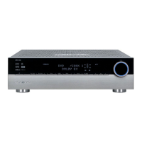
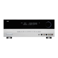
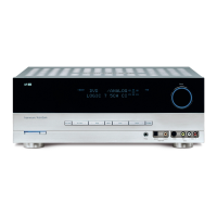
AVR1001 harman/kardon
 Loading...