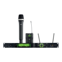
eQuiPment descriPtion
73
No. Description
6 Headphone buttons (CH1, CH2)
7 Headphone output: 6.3 mm jack socket
8 Infrared receiver window for data synchronization
9 HF level indicator
10 Channel selector button for channel CH1
11 Light ring for status display for channel CH1 and CH2 (red = warn‑
ing, green = OK)
12 Channel selector button for channel CH2
13 Opening for antenna front mounting
14 Antenna input A: BNC socket
15 Antenna input B: BNC socket
16 GROUND LIFT switch for XLR output from channel CH1
17 Balanced analog audio output, channel CH1, on XLR jack (male)
18 Unbalanced analog audio output, channel CH1, on 6.3 mm jack
socket
19 GROUND LIFT switch for XLR output from channel CH2
20 Balanced analog audio output, channel CH2, on XLR socket (male)
21 Unbalanced analog audio output, channel CH2, on 6.3 mm jack
socket
22 Data interface: RJ10 socket for connecting the receiver to a com‑
puter via HUB4000 Q
23 Dante™ output: Ethernet socket
24 AES‑EBU WORDCLOCK IN (48 kHz): BNC socket
25 Digital AES‑EBU audio output, CH1 and CH2 (48 kHz), to XLR
male socket)
26 IEC mains connection (100 – 240 V AC)
 Loading...