10
Front Panel Controls and Indicators
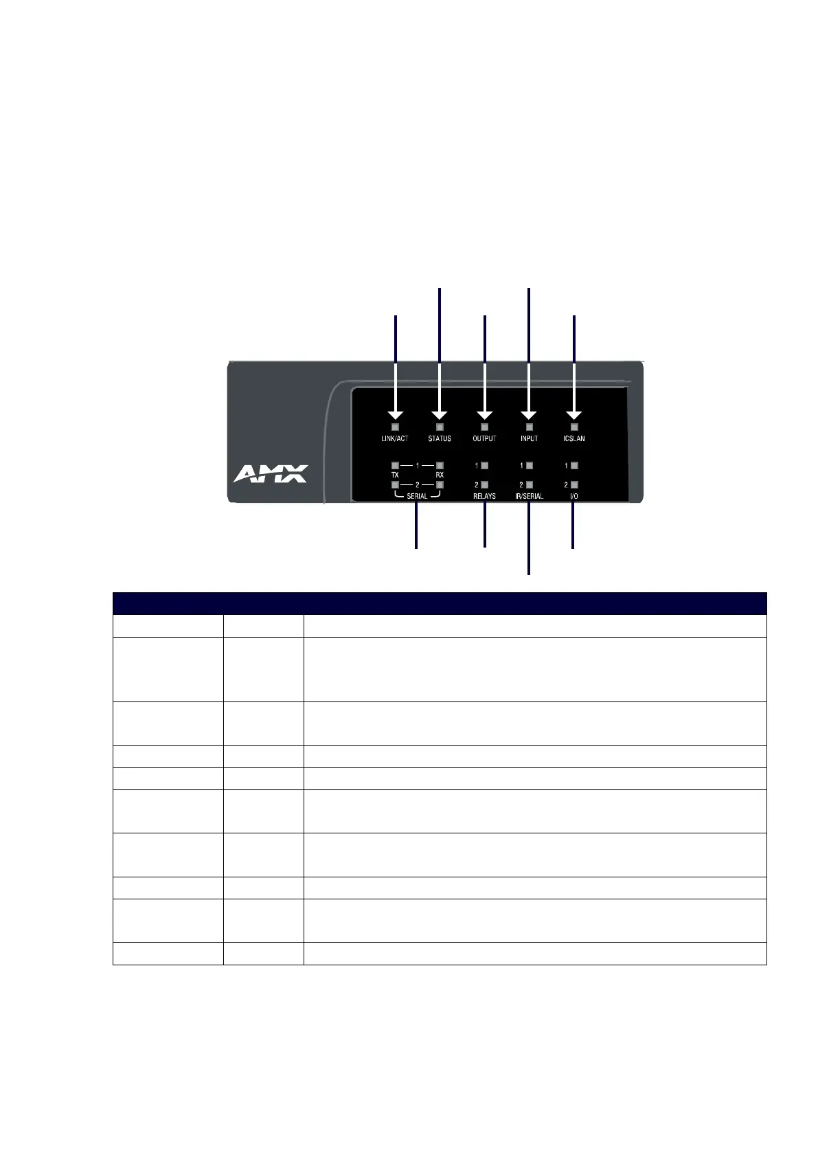
The following sub-sections describe each component on the front panel of the DVX. Refer to FIG. 1 for the
component layout of the front panel.
LEDs
The LEDs on the front panel indicate the communications status of several different connections. as
described in the table below:
SERIAL LEDs
LINK/ ACT LED
ICSLAN LEDOUTPUT LED
RELAY LEDs
I/O LEDs
Front Panel LEDs
Label Color Description
LINK/ACT Green
On indicates that the Ethernet cables are connected and terminated
correctly;
Blinking indicates receiving Ethernet data packets.
STATUS Green Blin
king indicates that the system is programmed and communicating
properly
INPUT Yellow Blinking indicates that the Controller is receiving data.
OUTPUT Red Blinking indicates that the Controller is transmitting data.
ICSLAN Red Blinking when the category cable to port 1 is connected and terminated
correctly.
SERIAL Red/Yellow Two LEDs indicate that the RS-232 port (1-2) is transmitting or receiving
data.
RELAY Red On indicates that relay channels are active on Port (21).
IR/SERIAL Red On indicates that IR/SERIAL channels are transmitting control data on Port
(11-12).
I/O Yellow On indicates that I/O channels are active on Port (22).
 Loading...