18
Green: Blinking when the audio data is being transmitted.
Yellow: Lights when the Dante enabled audio device is connected to the port.
Rear Panel Video Inputs and Outputs
The following sub-sections describe each component on the rear panel of the DVX. All digital inputs and
outputs on the DVX support HDCP2.2. Refer to Fig 2 & 3 of“Overview
” section for the component layout
of the rear panel.
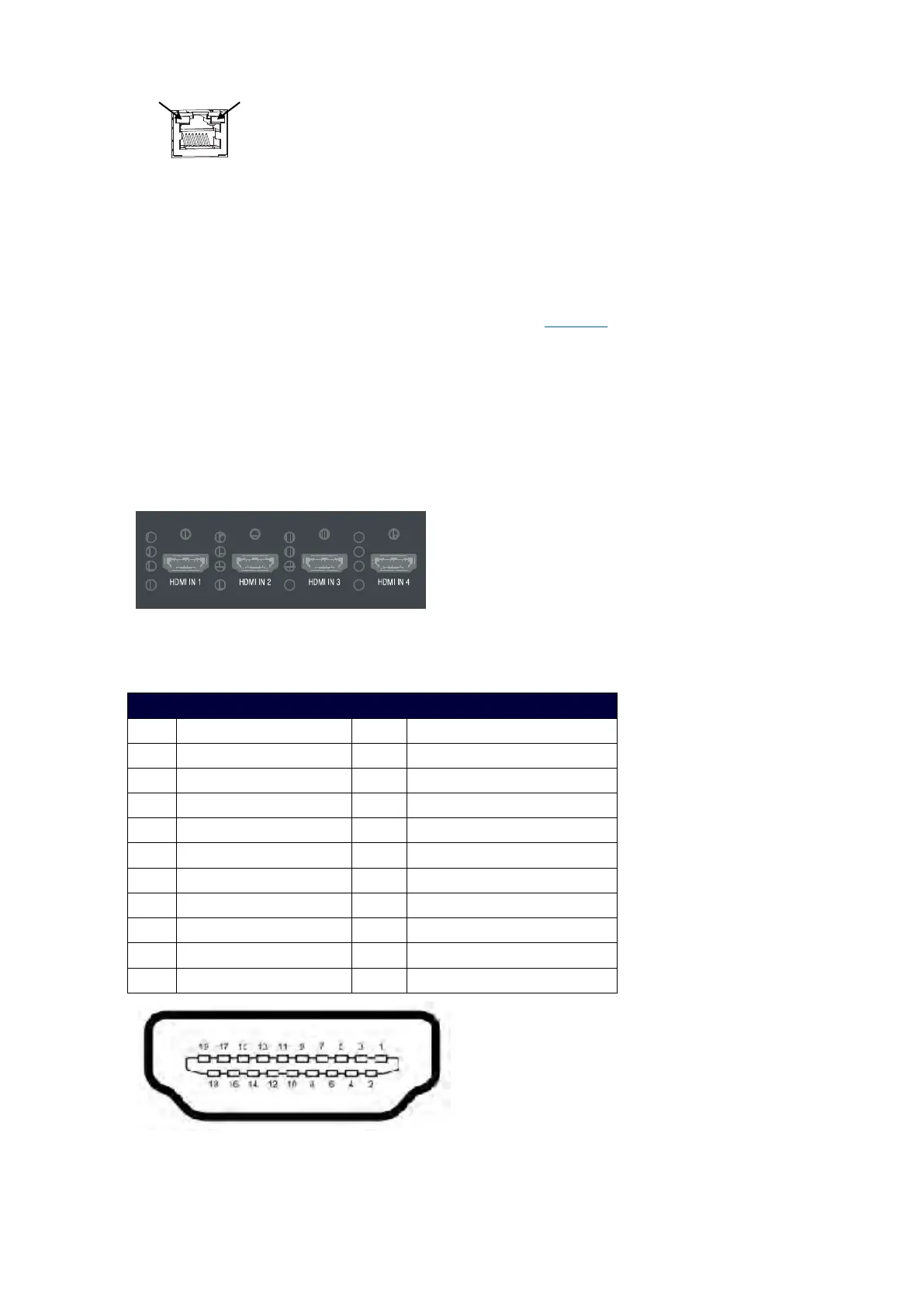
HDMI INPUTs
The HDMI INPUT connectors on the rear panel are used to connect source input devices to the DVX. The
DVX routes digital video and audio from connected source input devices to the connected output devices.
These ports support HDMI (with 3D and Deep Color) and HDCP 2.2.
These numbered inputs correspond to the input port number of the video signal when making a switch or
adjusting video input parameters.
The following table describes the pinout configuration of the HDMI INPUTS connectors:
HDMI INPUT Connectors – Pins and Signals
Pin Signal Pin Signal
1 TMDS Data 2+ 11 TMDS Clock Shield
2 TMDS Data 2 Shield 12 TMDS Clock-
3 TMDS Data 2- 13 CEC
4 TMDS Data 1+ 14 Reserved, HEC Data
5 TMDS Data 1 Shield 15 SCL
6 TMDS Data 1- 16 SDA
7 TMDS Data 0+ 17 DDC/CEC/HEC Ground
8 TMDS Data 0 Shield 18 +5V Power (max 50mA)
9 TMDS Data 0- 19 Hot Plug Detect, HEC Data+
10 TMDS Clock+ 20
 Loading...