EasyManua.ls Logo

Harmar Mobility Highlander CPL400 - User Manual

Harmar Mobility Highlander CPL400
22 pages
Print Icon
To Next Page IconTo Next Page
Loading...
This manual has been provided to assist
you with lift installation and operation.
For further assistance please contact
your authorized Harmar dealer or
Harmar’s Technical Service department.
Tel: 866-378-6648
Fax: 816-537-0641
CommercialPlatformLift
CPL400
CPL600
CPL800
CPL1000
CPL1200
CPL1400
HIGHLANDER
Question and Answer IconNeed help?

Do you have a question about the Harmar Mobility Highlander CPL400 and is the answer not in the manual?

Overview

The provided document is an installation and owner's manual for the Harmar Highlander Commercial Platform Lift.

Function Description:

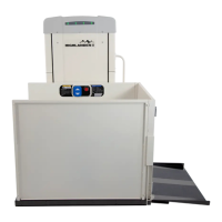
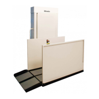
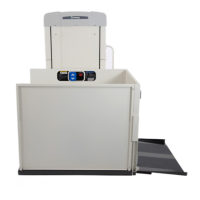
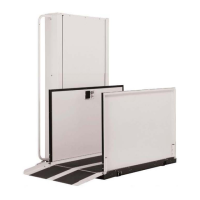
The Harmar Highlander Commercial Platform Lift is a vertical platform lift designed to provide accessibility for individuals using wheelchairs or those who require assistance with vertical mobility. It is intended for commercial use and is engineered to lift people and wheelchairs between different levels, such as from ground level to a raised landing, deck, or porch. The lift operates vertically and includes various safety features to ensure secure operation. It can be installed indoors or outdoors, with specific requirements for outdoor installations. The lift is designed to meet safety standards like ASME A18.1 section 2 and CSA B44/ASME A17.5, with additional options available to comply with varying local code requirements.

Important Technical Specifications:

  • Payload Capacity: 750 lbs (maximum).
  • Vertical Travel: 54" - 171".
  • Height: 77" - 197".
  • Foot Print: Varies depending on platform size and options.
  • Platform Size Options: 36" x 54", 36" x 60", or 42" x 60".
  • Input Voltage: 115vac - 20a.
  • Control Voltage: 24vac or 24vdc.
  • Platform Speed: 10 ft/min.
  • Motor: 1/2hp-90vdc or 1/2hp-24vdc.
  • Electrical Requirements: Requires a 115vac 20amp grounded circuit. Outdoor installations require a GFI protected circuit.
  • Installation Surface: Must be installed on a 4" thick, level 3,500 psi reinforced concrete slab.
  • Clearance Requirements:
    • Horizontal gap between platform edge and upper landing: 3/8" to 3/4".
    • Horizontal gap between guard panel and wall/barrier: 2" to 3".
    • Headroom above platform floor at upper landing: 6' 8".
    • Running clearance between platform edge and fascia panel: 3/8" to 3/4".

Usage Features:

  • Controls: The lift features a simple control panel with "UP" and "DOWN" rocker switches for movement. An emergency stop button is prominently located, which stops the lift when pushed in and allows operation when turned clockwise and pulled out. An optional keylock can disable controls when turned off, preventing unauthorized use.
  • Safety Pan: The platform is equipped with a sensor pan underneath. If pressure is applied to this pan (indicating an obstruction), the lift will not operate in the downward direction, preventing crushing hazards.
  • Auto-folding Ramp (Optional): This feature allows the access ramp to automatically fold and unfold as the lift moves, resting on the ground at the lower landing.
  • Top Landing Gate (Optional): This gate provides a mechanical lock and electric contact (interlock). It prevents the lift from running if the gate is not closed, and prevents the gate from being opened if the platform is not at the top landing. It unlocks when the lift reaches the upper limit switch. A crescent-shaped key is provided for manual unlocking during installation.
  • EMI and Flush Strike Interlocks (Optional): These interlocks are designed for use with existing doors at landings. They feature a combination mechanical lock and electric contact. They prevent the lift from running if the door is not closed and prevent the door from being opened if the platform is not at the landing.
  • Platform Gate (Optional): Similar to the top landing gate, this optional gate on the platform itself provides a mechanical lock and electric contact (interlock). It prevents the lift from running if the gate is not closed and prevents the gate from being opened if the platform is not at the bottom landing. It unlocks when the lift reaches the lower limit switch.
  • Call-Sends (Optional): These external controls can be mounted at upper and/or lower landings, allowing users to call the platform to their location or send it to the other landing.
  • Fascia Panel (Optional): A fascia panel provides a smooth vertical surface between the floor where the lift is mounted and the top landing. This eliminates pinch points and shear/obstruction hazards between the platform and landing.
  • Emergency Stop Switch: A critical safety feature that immediately stops the lift's operation when activated.
  • Manual Override: In case of a power failure, the lift is equipped with a manual handcrank to raise or lower the platform. This operation requires disconnecting power from the lift first.

Maintenance Features:

  • Limit Switches: The lift is equipped with adjustable upper and lower limit switches to ensure the platform stops level with the upper landing and at the correct position at the lower landing. The manual provides detailed steps for adjusting these switches.
  • Installation Instructions: The manual provides comprehensive, step-by-step instructions for installing the lift, including platform assembly, guard panel installation, ramp installation, anchoring, and electrical connections.
  • Troubleshooting (Implicit): While not explicitly a troubleshooting section, the manual's detailed installation and operation steps, along with warnings, guide users in identifying and preventing common issues. For instance, it instructs users to check the emergency stop switch, electrical connections, and circuit breaker if the lift doesn't run.
  • Warranty: The product comes with a limited warranty of two (2) years for material, mechanical, and electrical components (excluding labor, batteries, and paint), provided the lift is installed, maintained, and operated properly. If the CPL is installed outdoors without an Outdoor Package, the warranty is one (1) year. The warranty is void if the product is lost, damaged by accident, misused, neglected, or modified.
  • Technical Support: Harmar provides technical service for assistance with installation and operation, with a dedicated phone and fax number. Users are advised to contact their authorized Harmar dealer or Harmar's Technical Service department for further assistance or servicing.
  • Regular Verification: The manual emphasizes verifying the operation of the lift, including running cycles, emergency stop switch, and sensor pan, before training the customer and for continued safe use.

Harmar Mobility Highlander CPL400 Specifications

General IconGeneral
BrandHarmar Mobility
ModelHighlander CPL400
CategoryLifting Systems
LanguageEnglish

Related product manuals