8 5000/5100 Series Digital Analog Clocks Installation and Operation Manual
Chapter 1: DAC-5000 Series Digital Analog Clocks
Control Modes
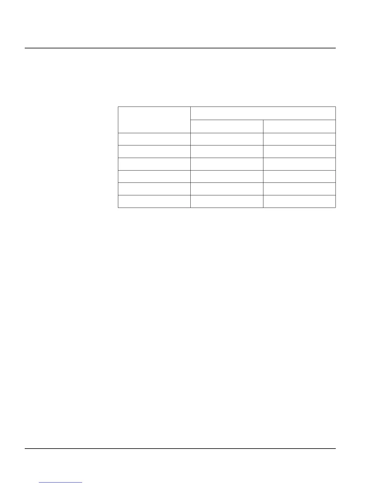
Table 1-4 lists the Clock Control mode DIP switch options.
Calibration of the Internal Time Base
This procedure is used to adjust the frequency of the 4.9152 crystal
oscillator. The accuracy of this adjustment directly affects the accuracy
of the Internal Time Base. The only equipment required is a high
resolution frequency counter.
Connect the frequency counter to the clock test point provided at pin 9
of the CMOS NSC800N Microprocessor IC11. Adjust the 6-25 pF
trimmer capacitor connected to pin 11 of IC11 until the counter
indicates 2.457.600 Hz. It is recommended to use the longest sampling
time possible.
Table 1-4. Clock Control Mode DIP switch options
Dip Switch
Switch Options
Open Closed
SW1 Timecode Impulse
SW2 SMPTE EBU
SW3 Internal Line
SW4 Normal Use offset
SW5 Normal Run on secondary
SW6 (Secondary) NA NA
 Loading...