5000/5100 Series Digital Analog Clocks Installation and Operation Manual 21
Chapter 2: ADC-5100 Series Analog Digital Clocks
Rear Panel
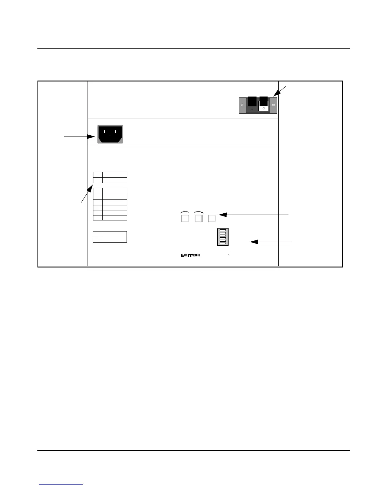
Figure 2-5. ADC-5108/5112/5116 Rear Panel
The rear panels of the ADC-5108/5112/5116 have two spring-loaded
speaker-type connectors (one red, one black) to accept the Primary
Reference input (i.e. SMPTE Serial Timecode or Impulse Drive
signals). Note that the correct polarity (i.e. red-to-red) is not required.
There is an indicator along the left side of the clock rear panel noting
whether the clock is in “MASTER” or “SLAVE” configuration. All
clocks are shipped configured for timecode input (slave) operation,
unless otherwise specified when ordering. The clock type and operating
voltage are also indicated on the rear panel.
A standard AC connector for the power feed of the unit can be found in
the recessed area running across the middle of the rear panel.
115/230 VAC 10%
50/60Hz
15VA Max
+
12 4356
OPEN
Time Code
SMPTE
Internal
Nor mal
Nor mal
Step Seconds
Impulse
EBU
Li ne
Use Offset
Run On Secondary
Sweep Seconds
115VAC
230VAC
OPERATION MODE
SLAVE
MASTER
ADC-5112
ADC-5108-L
ADC-5108
ADC-5116
ADC-5112-L
ADC-5116-L
Line Voltage
CW
CCW
MANUAL
SET
Multifunctional Pushbuttons
Full Instructions in Manual
Spring Loaded
“Speaker-Type”
Connectors (red
and black)
AC
Connector
(plug)
Push-Buttons:
CW, CCW,
MANUAL SET
DIP Switches
Clock Modes
(factory set)
 Loading...