18
HARTING Electric GmbH
19
Management Software Ha-VIS mCon Series / Edition 2.4
System SettingsUser Manual Ha-VIS mCon Switch Management Software
8. System Settings
The System Settings section is composed of the following sub-sections: General Settings, Port
Settings, User Management, SNMP, Network Discovery, Time Settings, DHCP Relay Agent and
File Transfer. All of this sections are described below.
8.1 General Settings and Switch Management
8.1.1 General Settings
In order to commission the Ethernet switch, the IP address and subnet mask must rst be modied
for the connected network (refer to the Quick-start Guide for setup instructions). If a DHCP server
(Dynamic Host Conguration Protocol) is running on your LAN, you can specify Dynamic in the
IP Address Mode settings.
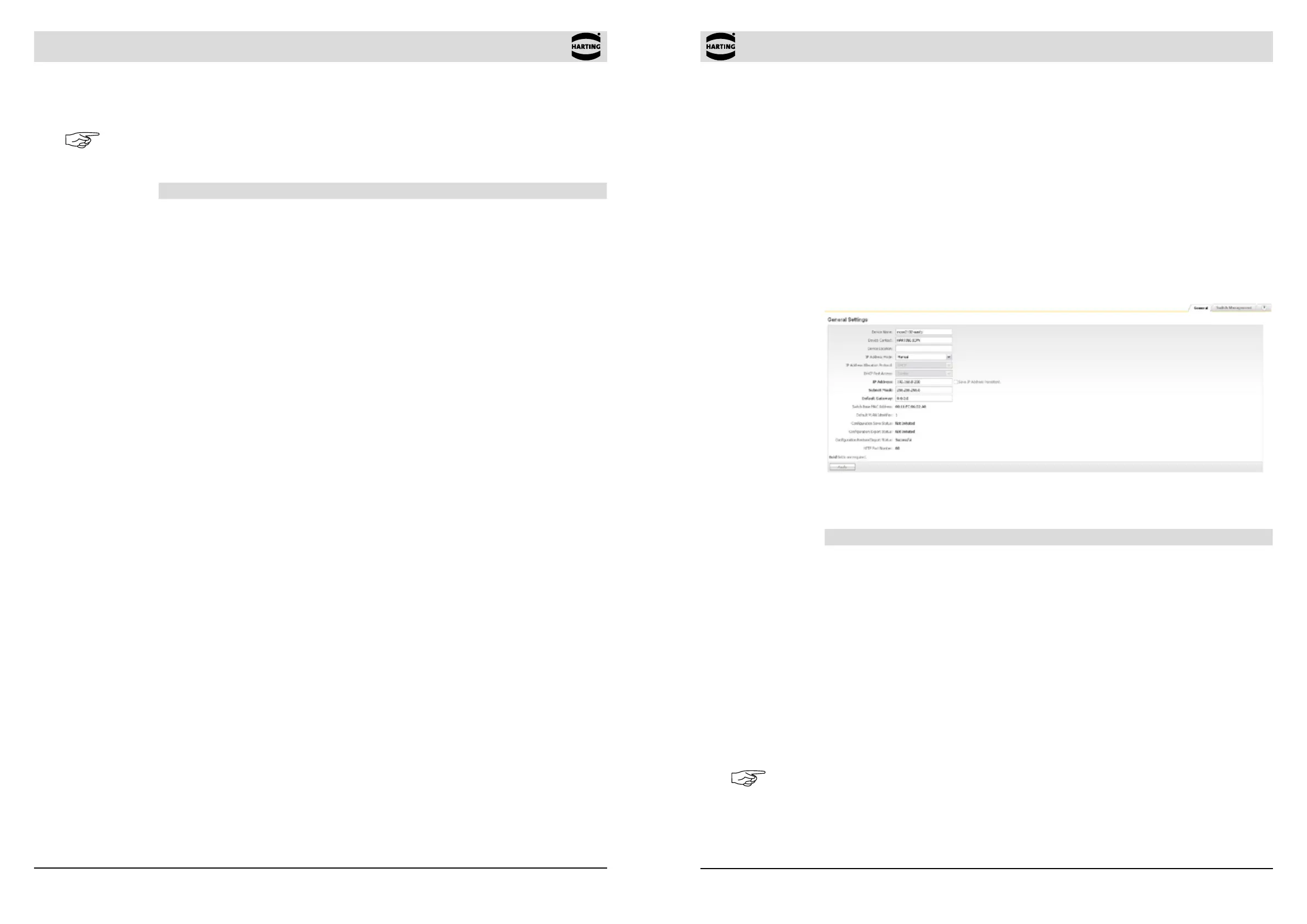
Figure 8-1 General Settings window
The following general settings can be displayed or specied:
Function Description
Device Name Specify a descriptive text for the device name.
Device Contact Specify a descriptive text for the device contact.
Device Location Specify a descriptive text for the device location.
IP Address Mode Specify the switch IP addressing mode. If Dynamic is selected in
the drop-down list, the switch is assigned with a valid IP address
and subnet mask during system initialisation by the DHCP server.
If Manual is selected, the IP address and the subnet mask must be
entered manually.
DHCP Fast Access The function accelerates the DHCP addressing in large networks.
The standard timeouts and waiting periods are reduced to a
minimum. It is recommended to set this option to enable, if Option
82 is used.
IP Address Specify the IP address of the switch. IP addresses are assigned
automatically if a DHCP server is activated.
Note
The IP address assigned to the switch must be unique for the respective network! Connectivity
problems will arise if two network components are assigned the same IP address.
The table at the bottom of the Overview window has the following columns for each port (see
table below).
Note
It is impossible to change information in the Overview window. Basic port settings can be altered
from the System Settings → Port Settings menu section.
Function Description
Port Displays all available switch ports.
Jack Type Displays the compatible media or jack type for the port (RJ45, or
SFP).
Status Displays the current status of the port. Enable means that the port is
enabled; Disable is displayed if the port is disabled. (A port can be
disabled in the System Settings → Port Settings section.)
Link Displays the status of the port. A red circle indicates that there is
currently no existing link, while a green circle indicates an existing
link.
Auto Neg Displays the negotiation state. Auto-negotiation is a technology for
ensuring compatibility of a network component with the network.
This column indicates if the Auto-negotiation function for the port is
activated (ON) or deactivated (OFF).
Data Rate Displays the data transfer mode for the respective port.
Duplex mode Displays the port duplex mode. Half duplex means that data ows in
one direction via the port at a given time; Full duplex enables data
ow in both directions.