DC Plug Polarity
The charging cables are connected to the DC output of the charger with the red cable to the
positive bus bar, and the black cable to the negative bus bar. The red cable is terminated into
the “+” side of the battery connector, and the black cable is terminated into the “-“side of the
connector. The output polarity of the charger must be observed when connecting to the battery.
Improper connection will open the DC fuses in the power modules.
DANGER: FAILURE TO GROUND THE CHARGER COULD LEAD TO FATAL ELECTRIC
SHOCK. Follow local and National Electric Code for ground wire sizing.
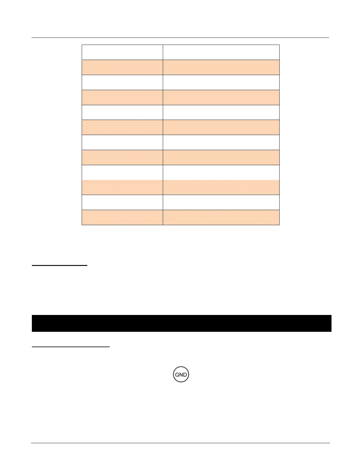
Grounding the Charger
Connect incoming grounding conductor to the ground lug provided on the charger support panel.
Torque the Ground wire to 15 in.lbs. This lug is marked as shown: