Table of Contents
Introduction Before You Begin................................................................... 1
Installation Steps.................................................................... 2
1. Preparing General Water Chemistry..................................................... 3
Pool/Spa Water Salt.......................................................................................... 4
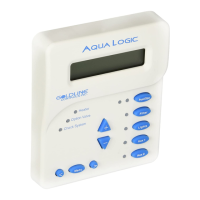
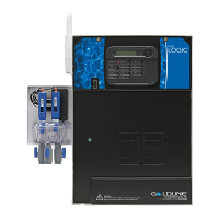
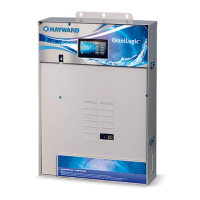
2. Mounting Pro Logic Control Center................................................... 5
Equipment PS-16 Expansion Unit.......................................................... 6
Temperature Sensors........................................................... 6
Optional Chlorination Function............................................ 6
Optional AQL-CHEM ORP and pH Sensing Kit................ 6
Optional AQL-COLOR-MODHV Network Module............. 6
Optional Wired Remote Display/Keypad........................... 7
Optional Wireless Remote Display/Keypad....................... 7
Optional Base Station........................................................... 7
Optional Valve Actuators....................................................... 7
3. Plumbing “Standard” Pool/Spa Configuration..................................... 8
“Dual Equipment” Pool/Spa - Separate Heaters............... 9
“Dual Equipment” Pool/Spa - Shared Heaters................... 10
Turbo Cell............................................................................... 11
Flow Switch............................................................................ 11
4. Electrical Main Service.......................................................................... 12
Wiring Grounding and Bonding........................................................ 12
Circuit Breaker Installation and Wiring................................ 12
General Purpose Outlet........................................................ 12
Pro Logic Control Power................................................... 13
High Voltage Pool Equipment.............................................. 13
Low Voltage Wiring............................................................... 15
5. Configuration Group Function...................................................................... 22
Configuration Menus............................................................. 24
Maintenance Menu................................................................ 40
6. System Startup Before Startup........................................................................ 41
and Checkout Heater Checkout.................................................................... 41
Service Mode........................................................................ 42
7. Warranty Pro Logic Limited Warranty................................................. 44
43
 Loading...