20
‘No Cell Power’ means the current chlorinator cycle has been interrupted due to no
voltage being detected when the cell power relay was turned on.
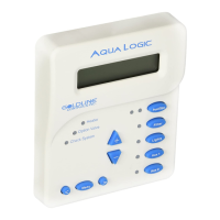
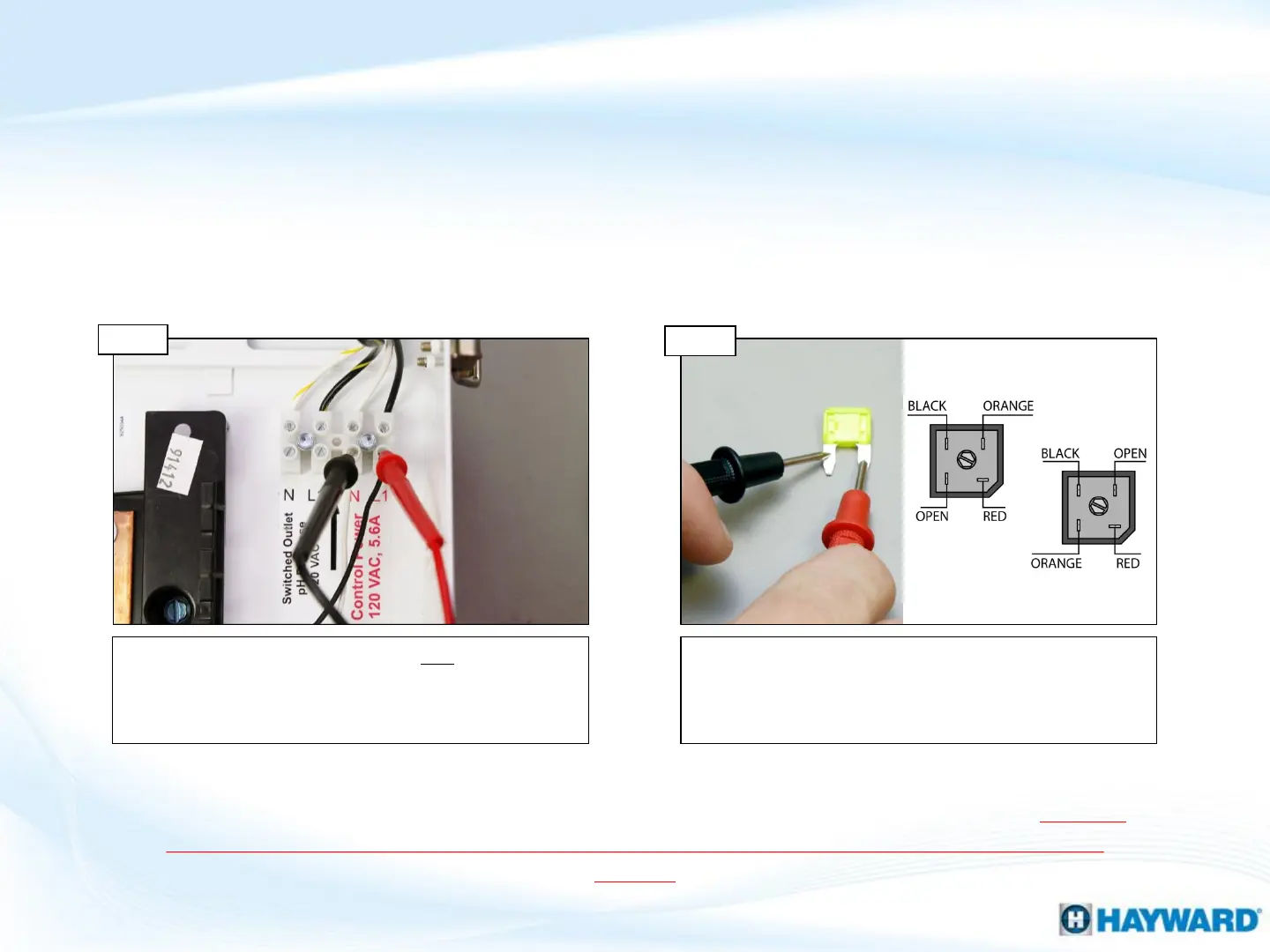
Verify the ProLogic is receiving 120VAC between the
black & white wires on the “Control Power” side of the
terminal block. IF no/low volts, correct at the breaker.
IF correct replace the main PCB board (see pg. 17).
Visually inspect & test the 20Amp fuse. IF fuse is blown,
replace it (GLX-F20A-10PK). IF fuse is OK, inspect the
rectifier wiring. IF rectifier wiring is correct, replace the
main board (see pg. 17).
PCB Input Power
Step 1C
Step 1D
NOTE: Verify the main board’s input power comes from positions 3 & 4 on the terminal block, which
is labeled “Control Power”. The two bottom left terminal blocks are factory installed for SENSE &
DISPENSE OUTPUT POWER ONLY, AND SHOULD NOT BE USED TO POWER THE MAIN SYSTEM
BOARD.
Inspect Fuse & Rectifier wiring
1. No Cell Power/Low Volts (cont.)
*