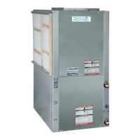
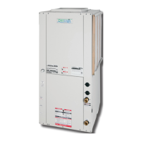
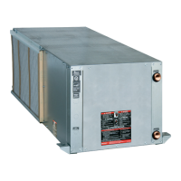
Heat Controller, Inc. HTV/HTD/HTH SERIES
6
2. Provide adequate clearance for filter
replacement and drain pan cleaning.
Do not block filter access with piping,
conduit or other materials. Refer to
unit submittal data or Engineering
Design Guide for dimensional data.
3. Provide access for fan and fan motor
maintenance and for servicing the
compressor and coils without removing
the unit.
4. Provide an unobstructed path to the
unit within the closet or mechanical
room. Space should be sufficient to
allow removal of the unit, if necessary.
5. In limited side access installations,
pre-removal of the control box side
mounting screws will allow control box
removal for future servicing.
6. Provide access to water valves and
fittings and screwdriver access to the
unit side panels, discharge collar and
all electrical connections.
Figure 1: Unit Mounting
Figure 2: Typical Unit Installation
Using Ducted Return Air
Internally insulate supply duct of first 15’
each way to reduce noise
Use turning vanes in supply transition
Flexible canvas duct connector to
reduce noise and vibration
Rounded return transition
Internally insulate return transition
duct to reduce noise
or Engineering Design Guide for
dimensional data.