26
(()
~
HEATHKIT
~
=tM@iH9i-M
~
White-blue wire to lug 1. (S-l ).
NOTE:
Do
not connect
this
wire to
lug
12
by
mistake.
(
t>(
Yellow
wire to lug 2 (S-1).
~
Orange
wire to lug 3 (S-1).
(~ White-violet.wire
to
lug 4
(S-1
1
).
(~
Brown
wire to lug 5 (S-1).
N)
Connect
the inner lead
of
the yellow
~
shielded cable .to lug
1~
(S-1). ·
(
Nt
Connect the inner lead
of
the red
:'!
~
..
,
'--
i!
n
"\
shielded cable to lug _6
(S-1
).
..
1-----
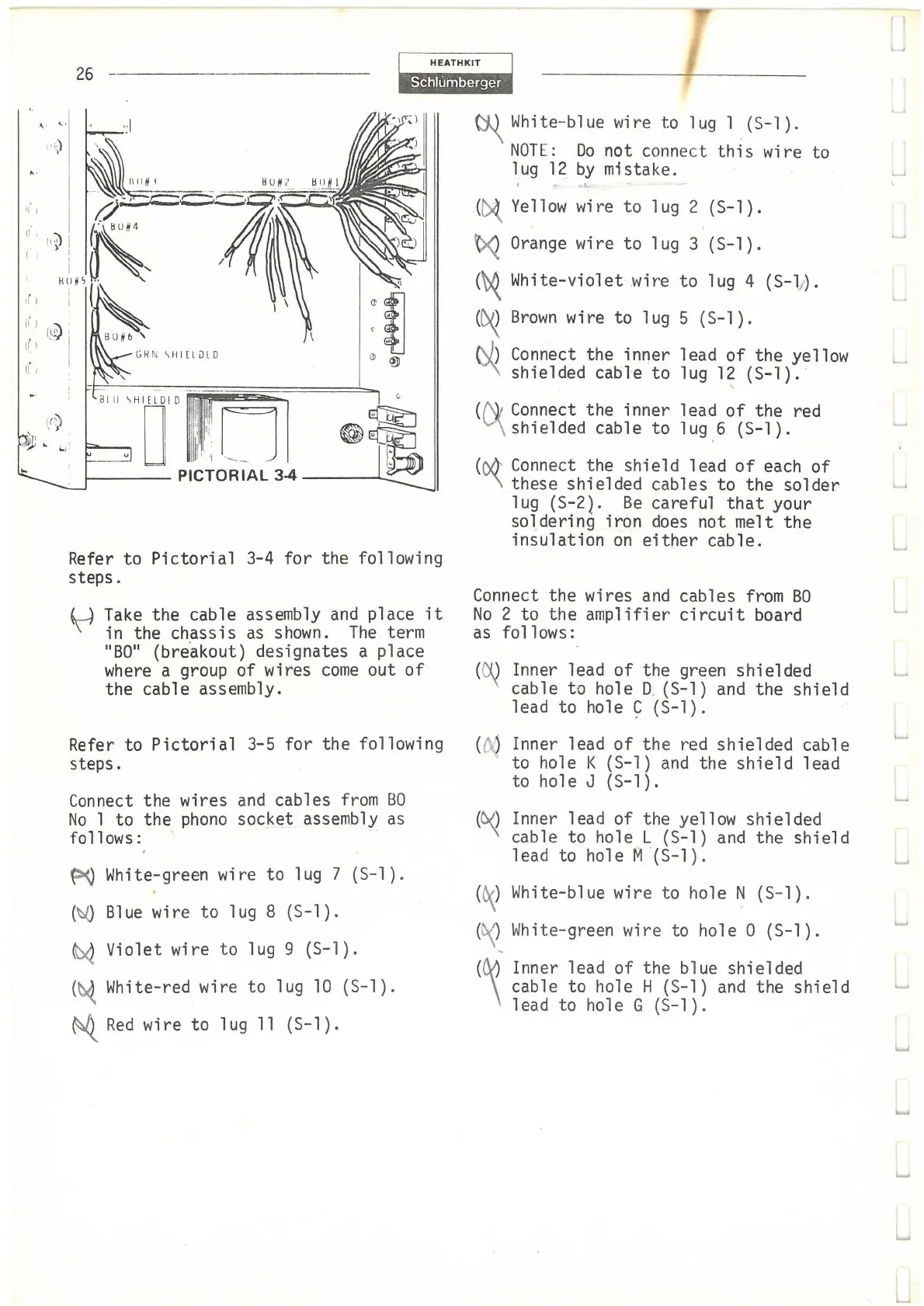
PICTORIAL 3-4
Refer to
Pictorial
3-4 for the following
steps.
Take
the cable assembly
and
place
it
in the chassis
as
shown.
The
term
11
B0
11
{breakout) designates a place
where
a group of wires
come
out
of
the cable assembly.
Refer to
Pictorial
3-5 for the following
steps.
Connect
the wires
and
cables
from
BO
No
1 to the
phono
socket assembly
as
follows: ·
~
White-green wire to lug 7
(S-1
).
(~
Blue
wire to lug 8 (S-1).
~
Violet wire to lug 9 (S-1).
(~ White-red wire
to
lug
10
(S-1).
~
Red
wire to lug
11
(S-1).
(
M'
Connect
the shield lead
of
each
of
v\
these shielded cables to the solder
lug (S-2}.
Be
careful
that
your
soldering iron
does
not melt the
insulation
on
either
cable.
Connect the wires
and
cables
from
BO
No
2 to the amplifier
circuit
board
as
follows:
(~ Inner lead
of
the green shielded
cable to hole D. (S-1)
and
the
shield
lead to
hole~
(S-1).
(~J Inner lead
of
the red shielded cable
to hole K (S-1)
and
the
shield
lead
to hole J (S-1).
(~ Inner lead of the yellow shielded
cable to hole L {S-1)
and
the shield
lead to hole M '(S-1).
(
O<_)
White-blue wire to hole N (S-1).
(\
')
White-green wire to hole O ( S-1).
~
(~ Inner lead
of
the blue shielded
cable to hole H (S-1)
and
the
shield
lead to hole G (S-1).
L
L.
L