I
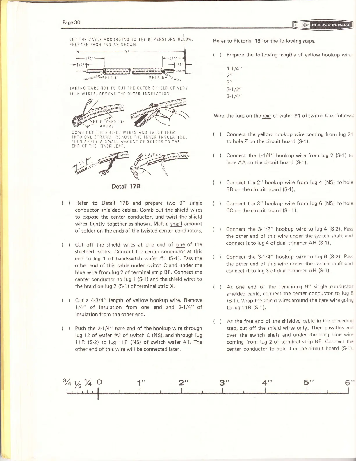
CUT THE
CABLT ACCORD
ING
TO THT D I['1ENS
IONS BELOW.
PREPARE
TACH
END
AS SHOWN.
IAKING
CART NOT TO CUT THE OUTER SHIILD
OF
VERY
THIN
WIRTS, RIMOVE THI OUTER
INSULATION.
COA4B OUT THt SHITLD \ryIRES AND TWIST THE[1
INTO ONT SIRAND. REA4OVT THE INNTR INSULATIO.,
THiN APPLY A SA4ALL A['iOUNT
OF
SOLDER
TO IHE
tND OF THI INNER LEAD-
Detail
178
(
)
Refer
to Detail
17B
and
prepare
two 9"
single
conductor
shielded cables, Comb out
the
shield
wires
to expose the
center
conductor, and twist the shield
wires
tightly together as shown.
Melt
a small
amount
of solder on the ends of the twisted
center conductors.
(
)
Cut off the shield wires
at one
end of one
of the
shielded
cables.
Connect
the center
conductor
at this
end to lug 1 of bandswitch wafer
#1
(S-1
).
Pass the
other end of this cable
under
switch
C and
under the
blue
wire from lug 2 of terminal
strip BF. Connect
the
center
conductor
to luq 1
(S-1)
and
the shield wires
to
the
braid
on lug
2
(S-1)
of terminal
strip
X.
(
)
Cut
a 4-314" length
of
yellow
hookup wire.
Remove
1
/4"
ol insu lation from one end and 2-1
14"
ot
insulation from the other end.
(
)
Push
the 2-1
14"
bare
end of the hookup
wire through
lug 12 of wafer
#2
of switch C
(NS),
and through
lug
11R
(S-2)
to lug
11F
(NS)
of switch wafer
#1.
The
other end of this wire will be connected
later.
Refer
to
Pictorial
18
for
the
following
steps.
(
)
Prepare
the
following lengths
of
yellow
hookup
wire
1-114"
2"
a'.
3-112"
3-114"
Wire the lugs on therear of wafer
#1
of switch C as
follows
(
)
Connect
the
yellow
hookup wire coming
from lug
21
to
hole
Z on the circuit
board
(S-1).
(
)
Connect
rhe 1-1
14"
hookup
wire
from lug
2
(S-1)
tc
hole
AA on the circuit board
(S-1).
()
(t
()
()
()
(t
Connect the
2"
hookup
BB on the circuit board
wire
from lug 4
(NS)
to
hol:
(s-1
).
Connect the
3" hookup wire
from lug
6
(NS)
to
hol:
CC
on the circuit board
(S-1).
Connect the 3-1
12"
hookup wire
to lug 4
(S-2).
Pass
the other end of
this wire under
the switch shaft
anc
connect
it
to
lug 4
of
dual trimmer
AH
(S-1).
Connect the 3-114"
hookup wire
to
lug
6
(S-2).
Pass
the other
end of this wire
under the switch shaft
anc
connect it to
lug
3 of dual
trimmer
AH
(S-1).
At
one
end of
the remaining
9" single
conducto"
shielded
cable,
connect the
center
conductor
to lug E
(S-1
).
Wrap the
shield
wires
around
the bare
wire
goin;
tolugllR(S-1).
At the
free end
of the shielded
cable
in the
precedin;
step,
cut
off the shield wires
only.
Then
pass
this
enc
over
the switch shaft
and
under
the long blue
wir:
coming
from lug 2 of
terminal strip
BF.
Connect
th:
center
conductor
to hole
J in the
circuit board
(S-1
2" 4"
5"
 Loading...