203HEIDENHAIN TNC 426 B, TNC 430
ú
Milling depth Q1 (incremental value): Distance
between the cylindrical surface and the floor of the
contour
ú
Finishing allowance for Q3 (incremental value):
Finishing allowance in the plane of the unrolled
cylindrical surface. This allowance is effective in the
direction of the radius compensation.
ú
Set-up clearance Q6 (incremental value):
Distance between the tool tip and the cylinder surface
ú
Plunging depth Q10 (incremental value):
Dimension by which the tool plunges in each infeed
ú
Feed rate for plunging Q11: Traversing speed of the
tool in the tool axis
ú
Feed rate for milling Q12: Traversing speed of the tool
in the working plane
ú
Radius Q16: Radius of the cylinder on which the
contour is to be machined
ú
Dimension type ? Q17: The dimensions for the rotary
axis of the subprogram are given either in degrees (0)
or in mm/inches (1)
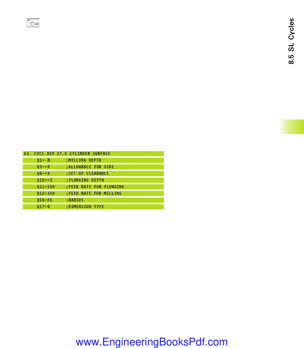
Example NC blocks:
63 CYCL DEF 27.0 CYLINDER SURFACE
Q1=-8 ;MILLING DEPTH
Q3=+0 ;ALLOWANCE FOR SIDE
Q6=+0 ;SET-UP CLEARANCE
Q10=+3 ;PLUNGING DEPTH
Q11=100 ;FEED RATE FOR PLUNGING
Q12=350 ;FEED RATE FOR MILLING
Q16=25 ;RADIUS
Q17=0 ;DIMENSION TYPE
8.5 SL Cycles
kkap8.pm6 30.06.2006, 07:03203
www.EngineeringBooksPdf.com
 Loading...


