Do you have a question about the HEIDENHAIN CNC PILOT 640 and is the answer not in the manual?
Explains safety precautions, hazard classifications (DANGER, WARNING, CAUTION, NOTICE), and the sequence of information in precautionary statements.
Details new functionalities introduced in various software versions, including specific G-codes and cycle enhancements.
Describes the three supported programming types: Conventional DIN/ISO, DIN PLUS, and smart.Turn, and how they can be combined.
Covers tool programming functions, including setting up the turret list and editing tool entries.
Explains various roughing operations like Longitudinal, Transverse, Contour-parallel, and Bidirectional roughing in ICP units.
Details recessing operations such as ICP contour recessing, recess turning, parting, and undercutting forms.
Provides an overview of thread units including direct, ICP, API, and tapered thread cycles.
Explains programming in ISO Mode, covering geometry and machining commands, NC blocks, and address parameters.
Provides an overview of milling cycles including linear slots, contour milling, area milling, helical slots, and pocket milling.
Details various datum shift functions (G51, G53-G55, G56, G59) for programming workpiece datums.
Covers inserting tools, correction of cut (G148), additive correction (G149), and tool tip compensation (G150/G151).
Details cycles for working with contours, including roughing (G810, G820, G830, G835), recessing (G860, G869, G870), and finishing (G890).
Provides an overview of drilling and boring cycles, including simple drilling (G71), boring/countersinking (G72), tapping (G73), and deep-hole drilling (G74).
Covers commands related to feed rate and spindle speed, including limitation (G26), interruption (G64), and reduction (G48).
Explains the fundamentals of TRC and MCRC and how to switch them off using G40.
Explains program branching using IF..THEN..ELSE..ENDIF, WHILE..ENDWHILE, and SWITCH..CASE statements.
Lists various touch probe cycles for automatic applications like calibration, measurement, and tool setting.
Details single-point measurement cycles for tool compensation (G770) and datum setting (G771, G772, G773).
Covers two-point measurement cycles for tool compensation (G775, G776, G777, G778) and calibration (G748).
Explains how to calibrate touch probes using standard methods (G747) or via two points (G748).
Describes measuring cycles for paraxial probing (G764), C axis probing (G765), ZX plane probing (G766), ZY plane probing (G768), and XY plane probing (G769).
Details cycles for finding holes and studs in C face and lateral surfaces (G780, G781, G782, G783).
Covers Y-axis milling cycles: Area milling (G841, G842), Centric polygon (G843, G844), Pocket milling (G845, G846).
Introduces TURN PLUS for creating programs with interactive graphics and automatic working plan generation.
Explains the AWG submode for generating work blocks, machining sequences, and control graphics.
Covers tool selection, turret assignment, contour recessing, drillg, cutting data, coolant, and speed limitation.
Details tool compensation during program run and how the control saves values in the tool database.
Details milling operations in the Y axis for face and lateral surfaces, including contours, pockets, deburring, and thread milling.
Lists milling cycles for face and lateral surfaces, predrilling cycles, contour and pocket milling, and engraving cycles.
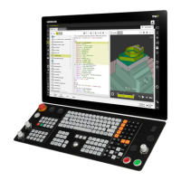
| Control Type | CNC |
|---|---|
| Resolution | 1024 x 768 pixels |
| Operating System | Windows |
| Interfaces | Ethernet, USB, Serial |
| Spindle Control | Yes |
| Tool Management | Yes |
| User Interface | Graphical user interface |
| Graphic Simulation | Yes |
| Display Type | TFT color display |
| Display Size | 15 inch |
| Processor | Intel |