6 – 394 HEIDENHAIN Technical Manual TNC 426, TNC 430
In the standard setting, the values of the Pt 100 inputs are taken over with a
change rate of 1 K/s. The disadvantage here is that for large changes in
temperature it can take a long time until the correct temperature reading is
attained. For example, it would take 30 seconds to correctly read a
temperature change of 30 K. An advantage of this, however, is a low
sensitivity to disturbance: the temperature display will not jump back and forth
between two values:
7
77
7 If you wish to work with a change rate of 1 K/s, set MP4020 bit 7 = 0.
7
77
7 If you wish to accept the values of the Pt 100 inputs immediately, set
MP4020 bit 7 = 1.
MP4020 PLC compatibility
Format: %xxxxxxxx
Input: Bit 7: Transferring the values of the Pt 100 inputs
0: Accept values at a change rate of 1 K/s
1: Accept results immediately
6.17.3 Analog Outputs
You can drive analog outputs 1 to 13 at sockets X8 and X9 (See "Mounting and
Electrical Installation” on page 3 – 5).
Module 9130 Output of an analog voltage
With this module you place an analog voltage on an analog output. The voltage
is output with a slight delay after the end of the PLC scan.
Call the module only once for each output per PLC scan!
Format: 1 mV
Voltages greater than +10 V or less than –10 V are limited to the respective
maximum value.
Call:
PS B/W/D/K <Number of the analog output>
1 to 6: Analog outputs 1 to 6 (X8)
7 to 13: Analog outputs 7 to 13 (X9)
PS B/W/D/K <Analog voltage in mV>
CM 9130
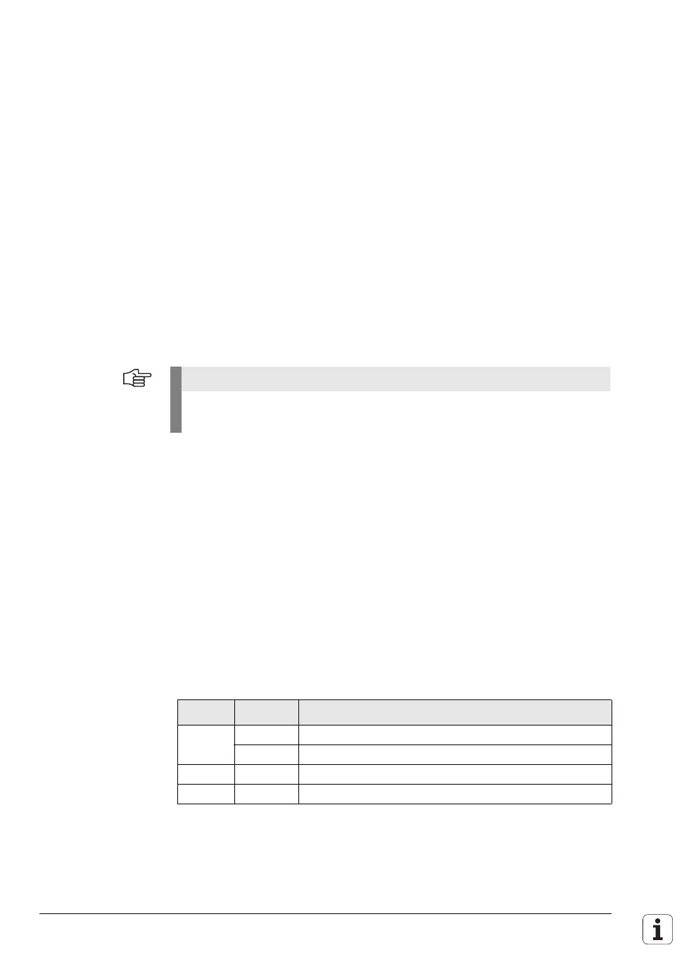
Error recognition:
Note
Every analog axis or analog spindle needs an analog output. These outputs
are no longer available to the PLC.
Marker Value Meaning
M4203 0 Analog voltage was output
1 Error code in W1022
W1022 1 Invalid analog output
2 Disabled analog output
 Loading...

