5
6
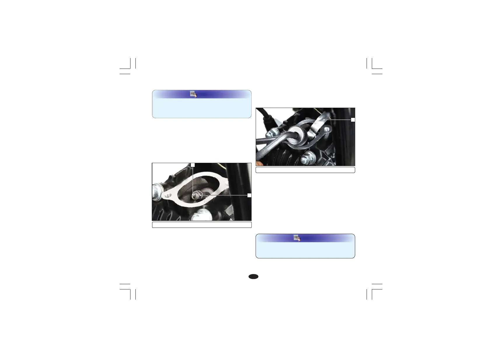
(5) Adjusting screw (6) Lock nut
The adjustment must be made when the
piston is at Top dead center and both the inlet
and exhaust valves are closed.
This condition can be determined by moving
the rocker arms. If they are free, it is an
indication that the valves are closed and the
piston is in compression stroke.
If they are tight the valves are open, rotate the
O
flywheel 360 anticlockwise and re-align the
'T' mark with the index mark.
(7) Feeler gauge
7
33
Ÿ Check the clearance by inserting the feeler
gauge (7) between the adjusting screw (5)
and valve stem tip.
Standard clearance (Cold condition )
Intake: 0.05 mm; Exhaust: 0.05 mm
Adjust by loosening the lock nut (6) and turning
the adjusting screw (5) until there is a slight drag
on the feeler gauge. After tightening the lock nut
(6), check again the clearance.
Ÿ Install the parts in the reverse order of
disassembly.
Before inserting the feeler gauge, smear a bit
of engine oil on the feeler gauge to avoid
damage to the feeler gauge.
NOTE
Adjustment
Ÿ Remove the crankshaft hole cap (1) and
timing hole cap (2) and tappet covers.
Ÿ Rotate the flywheel anticlockwise until
the 'T' mark (3) on the flywheel coincides
with the index mark (4) on the left crankcase
cover. In this position the piston will either be
on the compression or exhaust stroke.
The checking or adjusting of valve clearance
should be performed while the engine is cold.
The clearance will change as the engine
temperature rises.
NOTE