Harrington Generators International
19
498-1084 HRD060D Diesel Generator
Operation
(1) (2) (3)
(4) (5) (6) (7) (8)
Item
Description
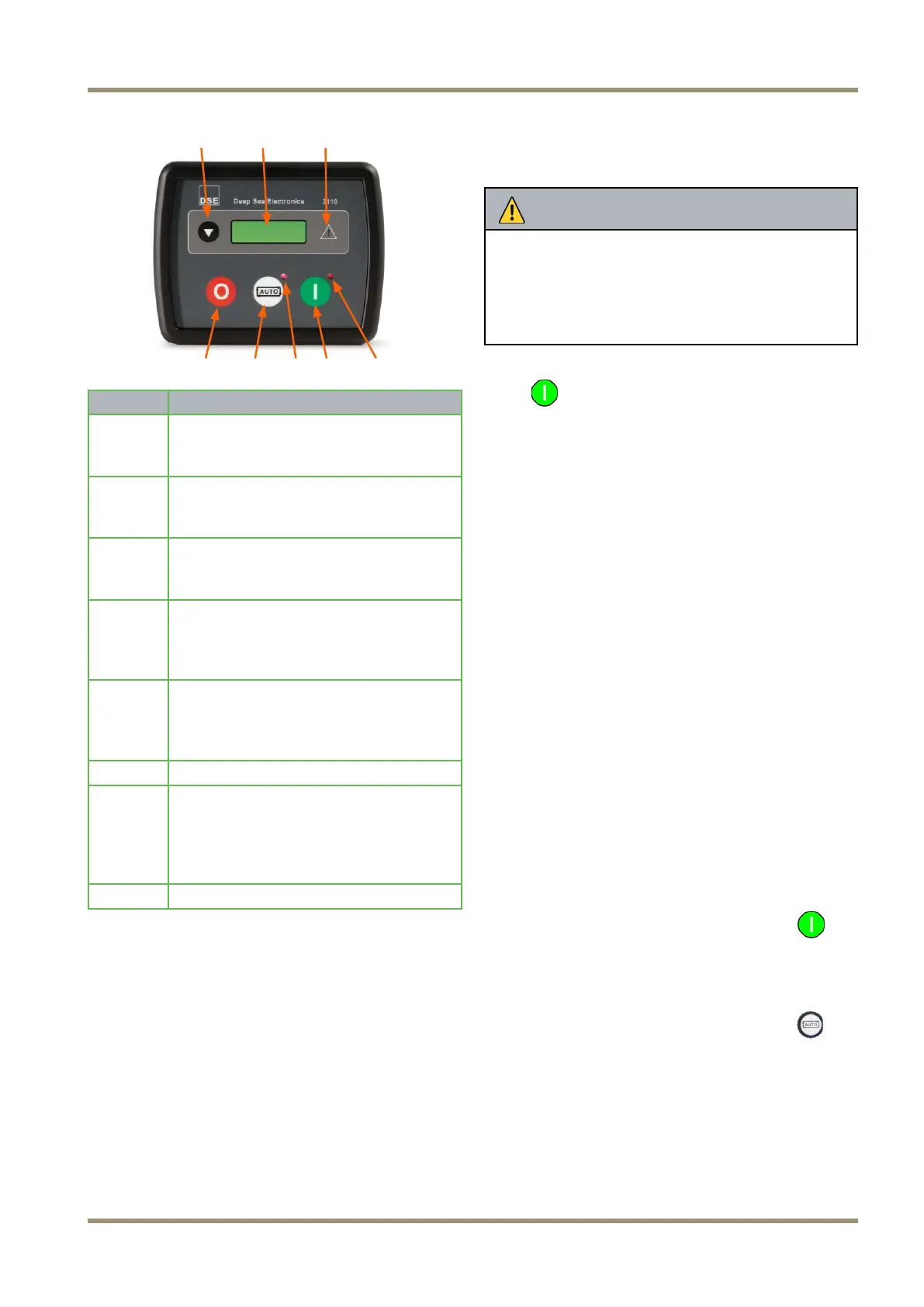
1
Navigation Button
Pressing this button scrolls the display
to show the various instruments.
2
Main Status Display
This displays the generator instrument
and alarm conditions.
3
Common Alarm Indicator
This illuminates when an alarm is
present.
4
Stop/Reset Button
This stops the generator and also
resets any alarms present (provided
the fault has been cleared).
5
Select “Auto” Mode
This places the set in ‘Automatic’
mode allowing the set to be operated
automatically and/or remotely.
6
Auto/Remote Indicator
7
Start Button
This button starts the engine. Press
once ONLY to start the engine. The
unit will automatically attempt up to
three starts.
8
Run Indicator
The Deep Sea 3110 is the main STOP / START
control unit for the generator. The control module
allows the user to control the operation of the
generator engine and also provides instrumentation
for;
• Engine Speed
• Generator Voltage
• Generator Frequency
• Engine Run Time (Hrs)
• Battery Volts
The DSE module will go into standby when no com-
mon alarms have been triggered after 1 minute of
inactivity. If the emergency stop is pressed the DSE
module will not go into standby.
NOTICE
Do not use Emergency Stop for routine stopping of
the generator or the Control Module will not go to
low power mode and discharge the battery.
Use the control Module “Stop” button to stop the
engine and when the engine has stopped turn the
control Module isolation switch to OFF.
To activate the control module press the green Start
button
once.
Instrumentation
To access various instrumentation displays you will
need to press the “page” button on the engine control
module. Each “page” of instrumentation can be ac-
cessed sequentially in this order.
• Engine speed
• Generator volts
• Generator frequency
• Engine run time
• Battery volts
If an alarm is raised while an instrumentation view is
being displayed the instrumentation view is changed
to the alarm page. The alarm page is only available
when an alarm has been raised; also the default
instrumentation view that is displayed is the engine
speed page.
Indicators
There are 3 indication LED’s (Light Emitting Diodes)
on the front of the engine control module;
1. The Started Mode Indicator
This LED is to the upper-right of the Start
button and is illuminated when the engine is in the
“Start” mode.
2. The Automatic Mode Indicator
This LED is to the upper-right of the Auto
button and is illuminated when engine control
module is in the “Auto” mode.
3. The Common Alarm Indicator
The type of common alarm is represented by an
Icon that can be seen in the large green LCD on
the control module. The Icons and the descrip-
tions of the the alarms they represent be seen
below: