Basic components
fuel tank, its funclion
is
as follows.
r
,,,,
"'il~
,,
~[1
幅
The 1uel tank supplied
with
th
ls engine Is
its dedicated fuel reservoir and
must
not
be
used as a fuel storage container. Com-
merclal users should
conform
to
relevant
IIcensing
or
approval
authority
reguia-
tions.
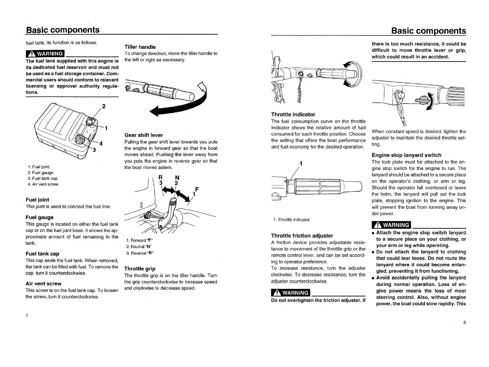
1.
Fuel
join
t
2.Fu
el
g
auge
3.
Fue
l la
nk
cap
4.
Air
v
ent
screw
Fuel
joint
了
his
joint
is
used to connecl Ihe
fu
e
llin
e
Fuel
gaug
.e
This gauge is located on either the fuel tank
cap or on the fuel
jo
int base. 1I shows the ap-
proximale amount
01
fuel remaining in the
tank
Fueltank
cap
This cap seals the
lu
el tank. When removed,
Ihe tank can be lilled wi
lh
lue
l.
To remove the
cap
, turn it
co
unterciockwise
Air
vent
screw
This screw is on the luel tank cap. To loosen
the screw
, turn it counterclockwise.
7
Tiller
handle
To change direction, mo
ve
the tiller handle to
the left or right as necessary
到
U
Throttle
indicator
The luel consumption curve
on
the throttle
indicator shows the relative amount
01
luel
consumed
lor
each Ihrottle posilion. Choose
the setting that olfers Ihe best performance
and luel economy
lor
the desired operation.
Gear
shift
lever
Pulling the gear shift lev
er
to
wa
rds you puts
the engine in lorward gear so that Ihe boat
mo
ves ahead. Pushing the lever away Irom
you puts the engine in reverse gear so th
al
the boal moves aslern.
1
1.
Thr
o
ttle
indi
ca
tor
1.
Forw
ard
宇
"
2.
Neut
ral "N"
3. R
ev
erse
"R"
Throttle
friction
adjuster
A Iriction device provides adjustable resis-
tance to movement
01
the throttle grip
or
the
remote controllever
, and can be set accord-
ing to operator prelerence.
To increase resistance
, turn the adjuster
clockwise. To decrease resistance
, turn the
adjuster counlerclockwise
Throtlle
grip
The throlt
le
grip is on the liller handle. Turn
the grip counle
rcl
ockwise
10
increase speed
and clockw
is
e 10 decrease speed
,
1
‘
""!':I~II~r
e'l
Do
not
overtighten
the
friction
adjuster
.
If
Basic
components
there
is
too
much
resistance,
it
could
be
difficult
to
move
throttle
lever
or
grip
,
which
could
result
in
an
acciden
t.
When constant speed is desired, lighten the
adjuster to maintain the desired throttle set-
ting
Engine
stop
lanyard
switch
The lock plate must be attached
10
the en-
gine stop switch
lor
the engine to
run
. The
lanyard should be attached to a secure place
on the operator's clothing
, or arm
or
¥
leg
Should the operator lall overboard or leave
the helm
, the lanyard will pull out the lock
plate
, stopping ignition to the engine. This
will prevent the boat Irom running away un-
der power
,?‘
.""!':I~II~
【帽
• Attach the
engine
stop
switch
lanyard
to
a secure place
on
your
clothing
,
or
your
arm
or
leg
while
operating.
• Do
not
attach
the lanyard
to
clothing
that
could
tear
loose.
00
not
route
the
lanyard where
it
could
become entan-
gled
,
preventing
it
from
functioning.
•
Avoid
accidentally
pulling
the la,nyard
during
normal
operation.
Loss
of
en-
gine
power
means
the
loss
01
most
steering
contro
l.
Also
,
without
engine
power
,
the
boat
could
slow
rapidly. This
8