19
ELECTRICAL INTERCONNECTION
INSTALLATION INSTRUCTIONS
BEFORE CONNECTING
For the professional installation of a sound system, car audio retail stores offers appropriate wire kits. Ensure a sufcient prole section
(at least 25 mm
2
), the suitable fuse rating and the conductivity of the cables when you purchase your wiring kit. Clean and remove rust-
streaked and oxidized areas on the contact points of the battery and the ground connection. Make sure that all screws are xed tight after
the installation, because loose connections cause malfunctions, insufcient power supply or interferences.
4
5
1
2
3
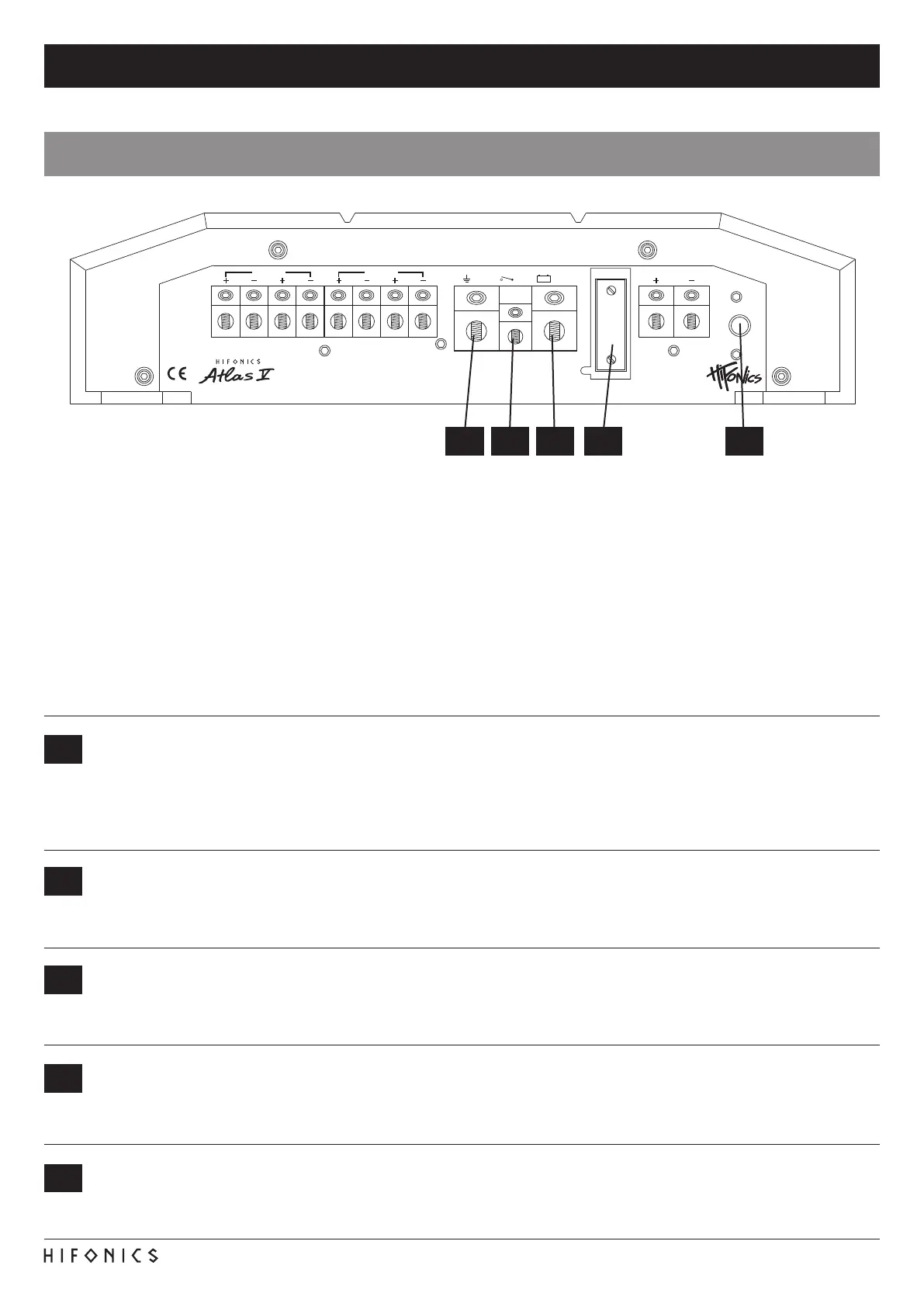
FUSE
The inserted fuses protect the amplier from shorts and capacity overload. The standard fuse is only suitable for a 4 ohm speaker
load. For a 2 ohm speaker load the current consumption increases by 50% and the fuse(s) may need to be replaced by fuses
with a higher rating.
LOGO
This push button switches the logo illumination on the upper side from blue to white.
GND
Connect this GROUND terminal with a suitable contact ground point on the vehicle’s chassis. The ground wire must be as short
as possible and must be connected to a blank metallic point at the vehicle’s chassis. Ensure that this ground point has a stable
and safe electric connection to the negative “–”pole of the battery. Check this ground wire from the battery to the ground point
if possible and enforce it, if required. Use a ground wire with a sufcient cross section (at least 25 mm
2
) and the same size like
the plus (+12V) power supply wire.
REM
Connect the turn-on signal (e.g. automatic antenna) or the turn-on remote signal of your head unit with the REM-terminal of the
amplier. Use therefor a suitable cable with a sufcient cross section (0,5 mm
2
). Hereby the amplier turns on or off with your
headunit.
BATT+12V
Connect the BATT+12V-terminal with the +12V pole of the vehicle’s battery. Use a suitable cable with a sufcient cross section
(at least 25 mm
2
) and install an additional in-line fuse. For safety reasons the distance between the fuseblock and the battery
should be shorter than 30 cm. Do not set in the fuse into the fuseblock until the installation is accomplished.
1 32 4 5
POWER INPUT
FUSE
SPEAKER OUTPUT
BRIDGED
PROTECT
POWER
LP/BPFULLHP
HP/BP LP
CH2CH1
LEVEL
INPUT
X-OVER
CH3/CH4
50Hz 250Hz 150Hz 4kHz
GND +12VREM
BRIDGED
CH4CH3
ARX5005
LEVEL
MIN MAX
FULLHP
X-OVER
CH1/CH2
HP
50Hz 4kHz
LEVEL
MIN MAX
MIN MAX15Hz 55Hz 0dB 18dB
SUB OUTPUT
4CH
35Hz 150Hz
HI
LOW
OFF
ON
CH3
CH4
CH1
CH2
CH5
BASS LEVEL
CONTROLLER
CH5
LEVELSUB SONIC BASS BOOST CH5LP
AUTO TURN ON
(ONLY IN HI LEVEL INPUT MODE)
LINE IN SUB IN
BLUE / WHITE
LOG0
 Loading...