Do you have a question about the HikRobot SC3000 Series and is the answer not in the manual?
Provides instructions for using and managing the Product, subject to change.
Lists Hikrobot's trademarks and logos as properties of Hikrobot.
States limitations of warranties, liability, and user responsibilities for product use.
Details FCC compliance for Class A digital devices and potential interference.
Outlines the two conditions for FCC rule compliance for the device.
Mentions CE marking and compliance with EMC and RoHS directives.
Defines symbols used in the document (Note, Warning, Danger) for clarity.
Confirms the manual applies to the SC3000 Series Vision Sensor.
States the device must be used in compliance with local laws and safety regulations.
Provides safety instructions for wiring, dismounting, and connecting the power supply.
Advises avoiding heavy pressure and vibration during handling to prevent damage.
Details environmental conditions to avoid for optimal operation and safety.
Outlines measures to prevent damage from static electricity during handling.
Instructs to contact service for issues and preserve original packaging.
Provides instructions for cleaning the image sensor using a clean rag and alcohol.
Advises against installing the product on vibrating or impact-prone surfaces.
Lists qualifications and skills needed for installation and maintenance personnel.
Provides company address, email, and website for support.
Introduces the SC3000 series vision sensor's capabilities and applications.
Lists key features like high-speed processing, algorithms, I/O interfaces, and protocols.
Provides power, input/output, Ethernet, and serial port signals.
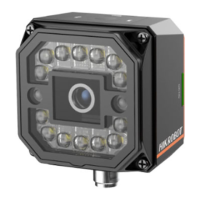
Indicates project results (green for OK, red for NG, yellow for errors).
Can be replaced with other lens caps for specific needs.
Refers to LED lamps providing light, with optional colors available.
Refers to the screw between the device body and lens cap.
Used to fix the device to the installation position with M4 screws.
Indicates power status (green for normal, red for abnormal).
Indicates device status (green for normal, red for error).
Indicates network status (flashing green for normal, unlit for abnormal).
Used to trigger image acquisition or switch projects.
Direct current power supply positive.
Can be configured as input or output.
Opto-isolated output.
RS232 serial port output.
RS232 serial port input.
Fast Ethernet signal MDI0+.
Fast Ethernet signal MDI1-.
Opto-isolated output.
Can be configured as input or output.
Opto-isolated output.
Signal ground, direct current power supply negative.
Input signal ground.
Can be configured as input or output.
Fast Ethernet signal MDI0-.
Fast Ethernet signal MDI1+.
Opto-isolated input.
Opto-isolated input.
Refers to tables and labels for wiring, recommends using the 17-pin cable.
Lists accessories needed for installation, like cables and screws.
Provides steps for installing the device, including fixing and connecting cables.
Guides through installing the SCMVS client software for configuration.
Recommends turning off Windows firewall for stable client operation.
Explains how to configure PC network settings for device communication.
Details how to set NIC properties like Link Speed and Duplex.
Explains how to set the device's IP address to match the PC's network segment.
Guides through logging into the client software with default credentials.
Describes the main window layout of the SCMVS client software.
Details the Menu Bar, Project Status, Tool Status, and Live View windows.
Outlines the general workflow for operating the device via the client software.
Introduces the electrical features of the device's I/O ports.
Explains input signal characteristics, logic levels, and delays.
Describes output signals and configurable I/O types (PNP/NPN).
Details how to set I/O output type (PNP/NPN) and control parameters.
Details output signal logic levels (low/high) and delays.
Describes two types of input wiring configurations for PNP and NPN devices.
Details the second method for configurable input signal wiring.
Explains how to wire the device's output signals to external devices.
Describes common serial ports (9-pin, 25-pin) and their pin functions.
Provides wiring diagrams for connecting the serial port to external devices.
Lists reasons (device not started, network issues) and solutions for software not listing devices.
Addresses issues with image smoothness and darkness, relating to network speed and settings.
Discusses reasons for no live view image, like trigger mode or network speed.
Provides steps to recover or reset the login password.
| Model | SC3000 Series |
|---|---|
| Category | Accessories |
| Product Series | SC3000 |
| Weight | Varies by model |
| Dimensions | Varies by model |
| Operating Temperature | -20°C to 60°C |
| Storage Temperature | -30°C to 70°C |
| Humidity | 10% to 90% non-condensing |