Quick Operation Guide of Digital Video Recorder
17
2. Press and hold the orange part of the pluggable block; insert signal cables into slots and release the orange
part. Ensure signal cables are in tight.
3. Connect Ta on controller to D+ on terminal block and Tb on controller to D- on terminal block. Fasten stop
screws.
4. Connect pluggable block back into terminal block.
Make sure both the controller and DVR are grounded. Here we take the controller connection of the
DS-8100HFHI-ST as an example.
Termination Switch Operation
This function is applicable to the DS-7300HFHI-ST&SL and DS-8100HFHI-ST&SL.
Purpose:
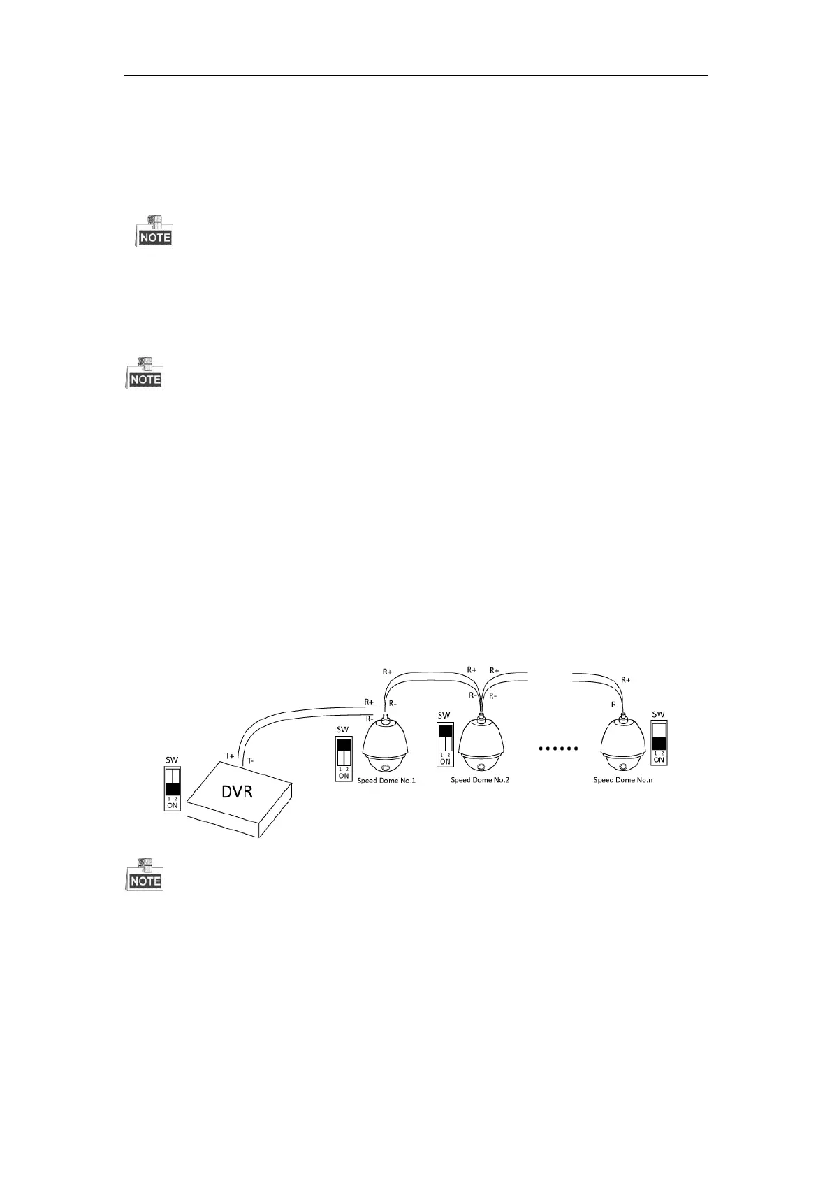
To connect the DVR with several speed domes, the bus topology can be adopted, which means the speed domes
are connected with each other via the R+ and R- of RS-485 serial interface. But due to the impedance of 485 wire,
the longer the wire is, the greater the impedance gets.
To avoid the signal reduction caused by the great impedance of long distance transmission, please connect two
120Ω resistors in the circuit: one resistor between the DVR and the nearest speed dome, and the other one after the
furthest speed dome.
Steps:
1. Turn on the SW switches on the DVR and the furthest speed dome.
2. Keep other SW switches off.
The connection diagram and status of each SW switch are shown in the following figure.
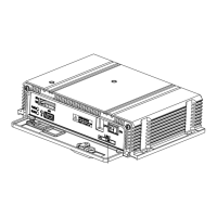
For the DS-7300HFHI-SL and DS-8100HFHI-SL series DVR, the termination switch is placed on the
mainboard instead of the rear panel. Open the upper cover and turn on/off the SW switch if needed.
 Loading...