Figure 3-56 Fix the Mounting Base
If required, you can route cables through the side opening on the side of the mounting base.
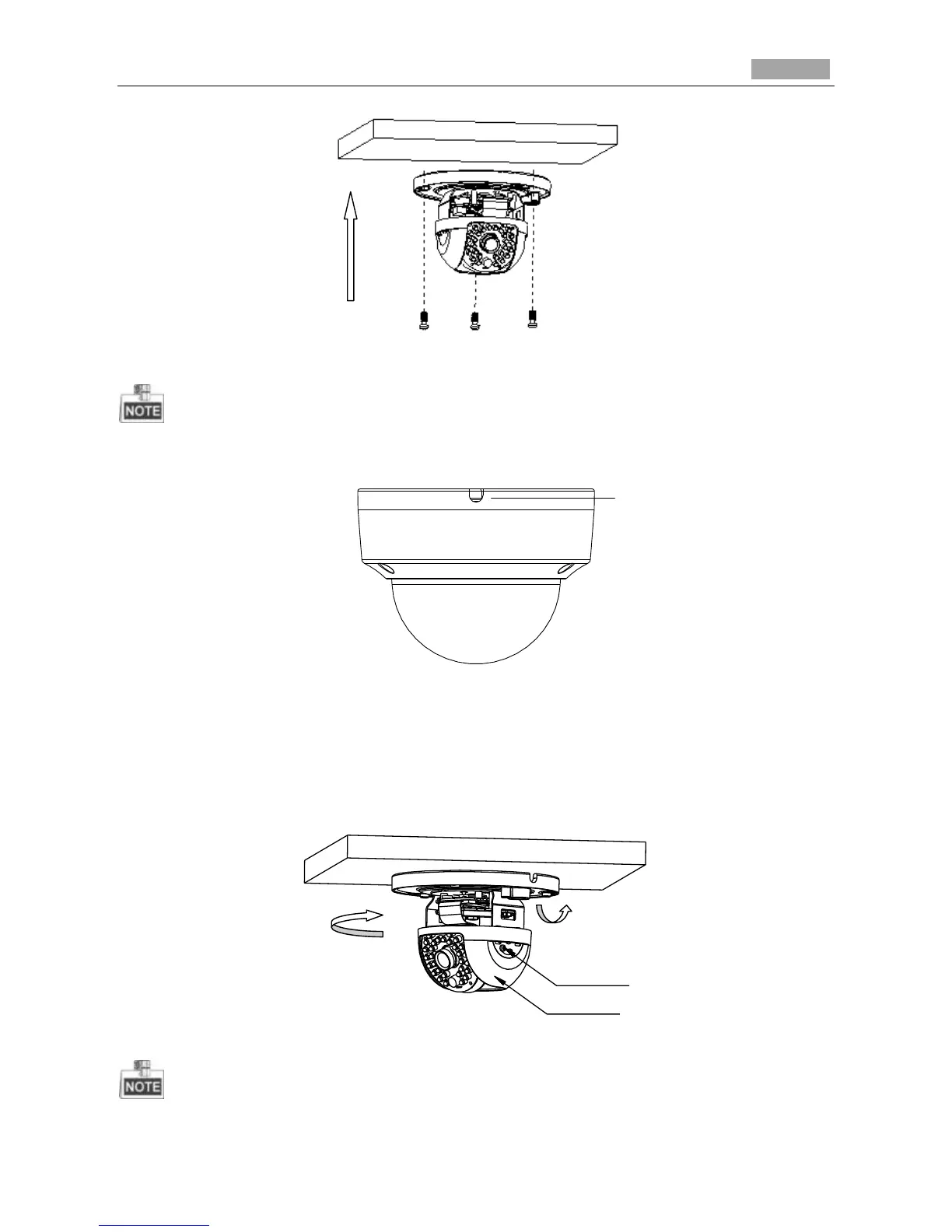
Figure 3-57 Side Opening
4. Loosen the tilt lock screws, adjust the tilting position in a range of 65 degrees, and tighten the tilt
lock screws.
5. Rotate the black liner to adjust the panning position in a range of 180 degrees until you get the
desired surveillance angle.