WI_Delivery Assist Trng CSM - DIR 50011929 ver F_2020-12-21 5
5. Assembly & Mounting – Option
DELIVERYASSIST-INS – Drilling Walls is Permitted
5.1. Depending on the supplied mounting option, select one of the following 5 mounting instructions –
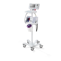
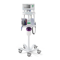
5.1.1. Assemble the Accessory Power Management (APM) #7000-APM roll stand following the instructions in the
7000-APM Assembly guide
1
5.1.2. Assemble the Classic MS3 Mobile #7000-MS3 stand as described in the 7000-MS3 assembly instructions
2
5.1.3. Assemble the 7000-GCX wall mount as described in the DU-WA-0015-01 assembly instructions
3
5.1.4. Assemble the CSM Integrated Wall Panel as described in the 80020744 assembly instructions
Please
refer to the Video in the LMS titled (CSM Integrated Wall Panel Mounting instructions) for guidance on
installation steps. CSM Integrated Wall Panel Mounting instructions
5.1.5. Assemble the “30 inch” CSM Integrated Wall Panel as described in the 80021929 assembly instructions
5.2. If the order includes a Barcode scanner - Install the Barcode scanner holster, see 7000-Holster guide
4
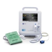
5.3. The battery needs to be connected before use
5.3.1. Open the battery cover and connect the battery, see instructions on CSM Startup Guide
5
, step 1
5.4. Place the CSM on the Roll Stand mounting option:
5.4.1. Refer to the CSM Startup Guide
5
, section A, for the 7000-MS3 classic stand and section B for the 7000-
APM roll stand mounting instructions.
5.4.1.1. The MS3 Power adapter is to be mounted onto the bottom side of the basket of the mobile
stand as displayed in the graphic on page 77 of the CSM Service Manual
6
To mount the CSM on the APM mobile stand, refer to the APM mounting instructions in the
CSM startup Guide
5
, section B.
Note: For easy access while mounting, it is advised to plug in the USB and power cable from the APM into
the CSM and also connect any other connector that goes into the bottom housing of the CSM (NIBP,
SpO2, SureTemp) before fixing the CSM onto the APM roll stand as shown in the startup Guide
5.4.1.2. To mount the CSM monitor on the 7000-GCX wall mount – follow the steps as described in the
7000-GCX assembly instructions Error! Bookmark not defined.
6. Connect accessories
6.1. In case of the Wall mount or Classic stand, connect the accessories according to Steps 3A of the CSM Startup
Guide Error! Bookmark not defined.
6.2. When using the APM, the accessories have already been connected as part of the assembly procedure in step
4.1.1./5.1.1.
6.3. Affix customer provided asset tag on the location that is agreed upon with the customer.
 Loading...