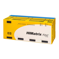
F2 DO 16 02 3 Product Description
HI 800 139 E Rev. 2.00 Page 15 of 42
3.4.1 Safety-Related Relay Outputs
The remote I/O is equipped with 16 safety-related relay outputs. Each relay output is switched
via three relays connected in series. One relay is a standard relay, whereas the two other relays
are safety relays with forcibly guided contacts (EN 50205).
All 16 relay outputs are electrically safely separated from one another and from the power
supply of the device. For safe separation, the air and creeping distances are designed in
accordance with IEC 61131-2 for overvoltage class II up to 300 V.
The relay outputs are connected with numbered cable plugs. To facilitate the assignment of the
individual relay outputs, an identical number is located on the front plate of the remote I/O, see
Chapter 4.1.1.
The termin
al connections and the housing comply with IP20 protection requirements. With
higher requirements, the F2 DO 16 02 must be mounted in an enclosure with suitable type of
protection.
If voltages other than SELV and PELV are connected, cables with suitable insulation must be
used.
The state of each relay output is signaled by an individual LED, see Chapter 3.4.2.
3.4.1.1 Burner Control Applications
For burner control applications, an internal fuse is used to limit the relay outputs switching
current to 60 % (3.15 A) of the maximum permissible value in accordance with EN 298 and
EN 50156-1 (VDE 0116). The relay outputs can be used for safety shutdowns, i.e., to shutdown
the entire fuel supply.
If burner control applications require a reduced switching current (AC/DC) than the limited
switching current (3.15 A), an external pre-fuse must be switched into the circuit.
The relays in use comply with the contact lifetime required for burner control applications:
mechanical ≥ 3 x 10
6
switching operations
electrical ≥ 250 000 switching operations

 Loading...