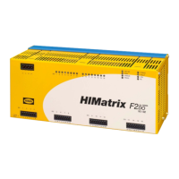
F2 DO 16 02 4 Start-up
HI 800 139 E Rev. 2.00 Page 25 of 42
Terminal Designation Function (relay output 11)
21 DO11 Contact 11, terminal A
22 DO11 Contact 11, terminal B
Terminal Designation Function (relay output 12)
23 DO12 Contact 12, terminal A
24 DO12 Contact 12, terminal B
Terminal Designation Function (relay output 13)
25 DO13 Contact 13, terminal A
26 DO13 Contact 13, terminal B
Terminal Designation Function (relay output 14)
27 DO14 Contact 14, terminal A
28 DO14 Contact 14, terminal B
Terminal Designation Function (relay output 15)
29 DO15 Contact 15, terminal A
30 DO15 Contact 15, terminal B
Terminal Designation Function (relay output 16)
31 DO16 Contact 16, terminal A
32 DO16 Contact 16, terminal B
Table 15: Terminal Assignment for the Relay Outputs
4.1.2 Cable Plugs
Cable plugs attached to the pin headers of the devices are used to connect to the power supply
and to the field zone. The cable plugs are included within the scope of delivery of the HIMatrix
devices and modules.
The devices power supply connections feature the following properties:
Connection to the power supply
Cable plugs Four poles, screw terminals
Wire cross-section 0.2…2.5 mm
2
(single-wire)
0.2…2.5 mm
2
(finely stranded)
0.2…2.5 mm
2
(with wire end ferrule)
Stripping length 10 mm
Screwdriver Slotted 0.6 x 3.5 mm
Tightening torque 0.4…0.5 Nm
Table 16: Power Supply Cable Plug Properties
Connection to the field zone
Number of cable plugs 2 pieces, eight poles, screw terminals
Wire cross-section 0.2…1.5 mm
2
(single-wire)
0.2…1.5 mm
2
(finely stranded)
0.2…1.5 mm
2
(with wire end ferrule)
Stripping length 6 mm
Screwdriver Slotted 0.4 x 2.5 mm
Tightening torque 0.2…0.25 Nm
Table 17: Input and Output Cable Plug Properties

 Loading...