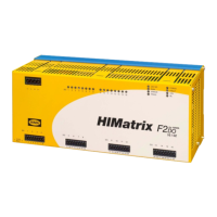
4 Start-up F2 DO 16 02
Page 24 of 42 HI 800 139 E Rev. 2.00
4 Start-up
To start up the remote I/O, it must be mounted, connected and configured in the programming
tool.
4.1 Installation and Mounting
The remote I/O is mounted on a 35 mm DIN rail such as described in the HIMatrix System
Manual.
When laying cables (long cables, in particular), take appropriate measures to avoid interference,
e.g., by separating the signal lines from the power lines.
When dimensioning the cables, ensure that their electrical properties have no negative impact
on the measuring circuit.
i
If voltages other than SELV and PELV are connected, suitable cables with double or increased
insulation must be used, e.g., power cables.
4.1.1 Connecting the Digital Outputs
Use the following terminals to connect the digital outputs:
Terminal Designation Function (relay output 1)
1 DO1 Contact 1, terminal A
2 DO1 Contact 1, terminal B
Terminal Designation Function (relay output 2)
3 DO2 Contact 2, terminal A
4 DO2 Contact 2, terminal B
Terminal Designation Function (relay output 3)
5 DO3 Contact 3, terminal A
6 DO3 Contact 3, terminal B
Terminal Designation Function (relay output 4)
7 DO4 Contact 4, terminal A
8 DO4 Contact 4, terminal B
Terminal Designation Function (relay output 5)
9 DO5 Contact 5, terminal A
10 DO5 Contact 5, terminal B
Terminal Designation Function (relay output 6)
11 DO6 Contact 6, terminal A
12 DO6 Contact 6, terminal B
Terminal Designation Function (relay output 7)
13 DO7 Contact 7, terminal A
14 DO7 Contact 7, terminal B
Terminal Designation Function (relay output 8)
15 DO8 Contact 8, terminal A
16 DO8 Contact 8, terminal B
Terminal Designation Function (relay output 9)
17 DO9 Contact 9, terminal A
18 DO9 Contact 9, terminal B
Terminal Designation Function (relay output 10)
19 DO10 Contact 10, terminal A
20 DO10 Contact 10, terminal B
 Loading...