4 Start-up CPU 03
Page 22 of 38 HI 800 479 E Rev. 1.00
4.2 Numbering of Slots
Slots 1 and 2 on the F60 subrack are reserved for the PS 01 power supply module and
CPU module, respectively. Any type of I/O modules can be plugged in to slots 3...8.
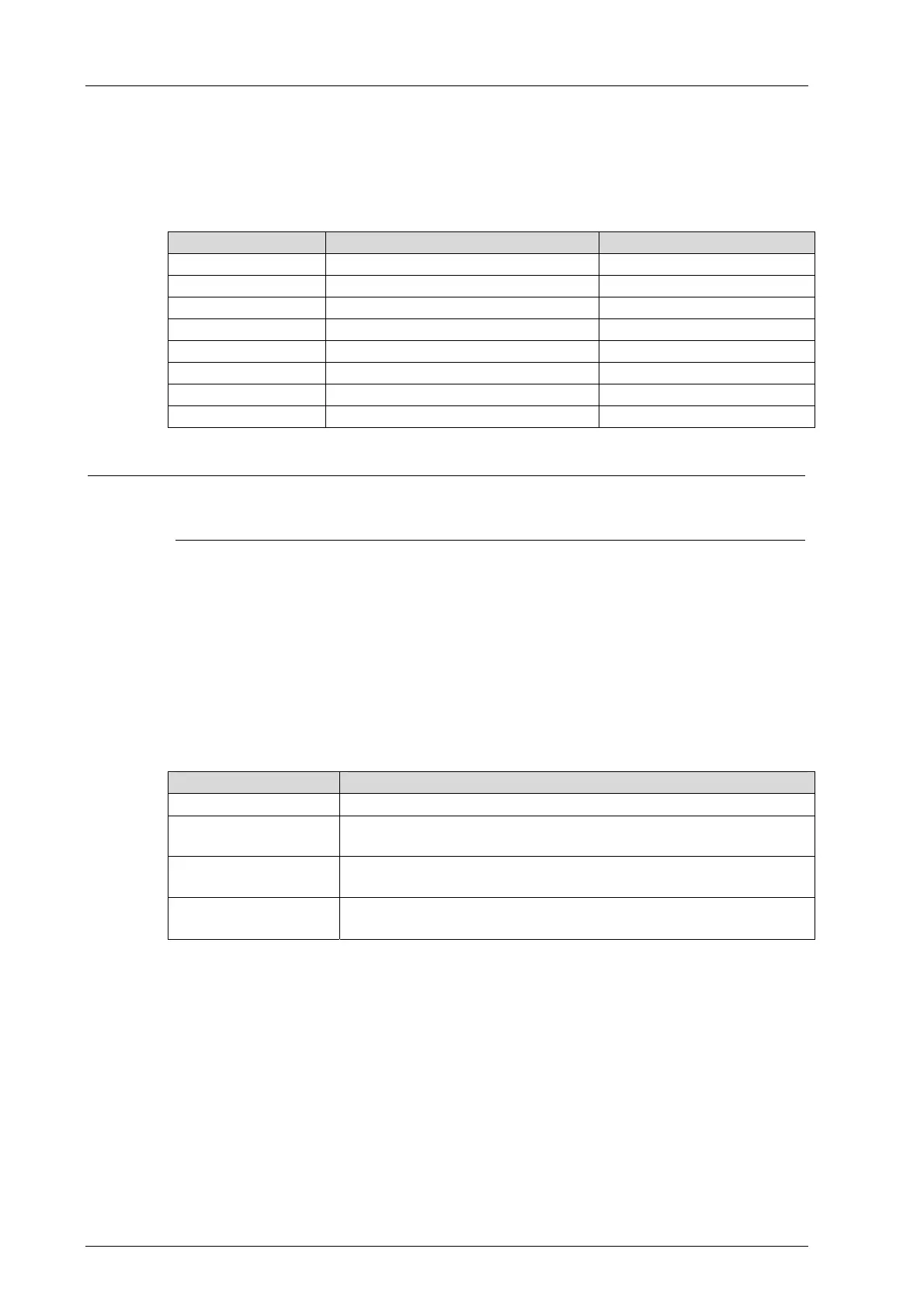
The module slots in SILworX are numbered as follows:
Module Slot on the rack Slot in SILworX
PS 01 1 -
CPU/COM 2 0/1
I/O 3 2
I/O 4 3
I/O 5 4
I/O 6 5
I/O 7 6
I/O 8 7
Table 14: Module Slots
i
The PS 01 power supply module is not configured.
CPU and COM are both on the F 60 CPU 03 module. In the programming tool SILworX,
however, they are represented as separated items.
4.3 Sequence of Events Recording (SOE)
Global variables of the controller can be monitored using the sequence of events recording.
Global variables to be monitored are configured using the programming tool SILworX, see
the online help and the SILworX Communication Manual (HI 801 101 E). Up to 4000 events
can be configured.
An event is composed of:
Entry data Description
Event ID The event ID is assigned by the PADT.
Timestamp Date (e.g., 21/11/2008-21)
Time (e.g., 9:31:57.531)
Event state Alarm/Normal (boolean event)
LL, L, N, H, HH (scalar event)
Event quality Quality good/
Quality bad, see www.opcfoundation.org
Table 15: Event Description
Events are recorded within the cycle of the user program. The processor system uses
global variables to create the events and stores them in its non-volatile event buffer.
The event buffer includes 1000 events. If the event buffer is full, an overflow system event
entry is created. Thereafter, events are no longer recorded until existing events have been
read and space is once again available in the event buffer.

 Loading...


