(APPENDIX IV) DIMENSIONS, WIRING AND MECHANICAL PARTS | PAGE 56
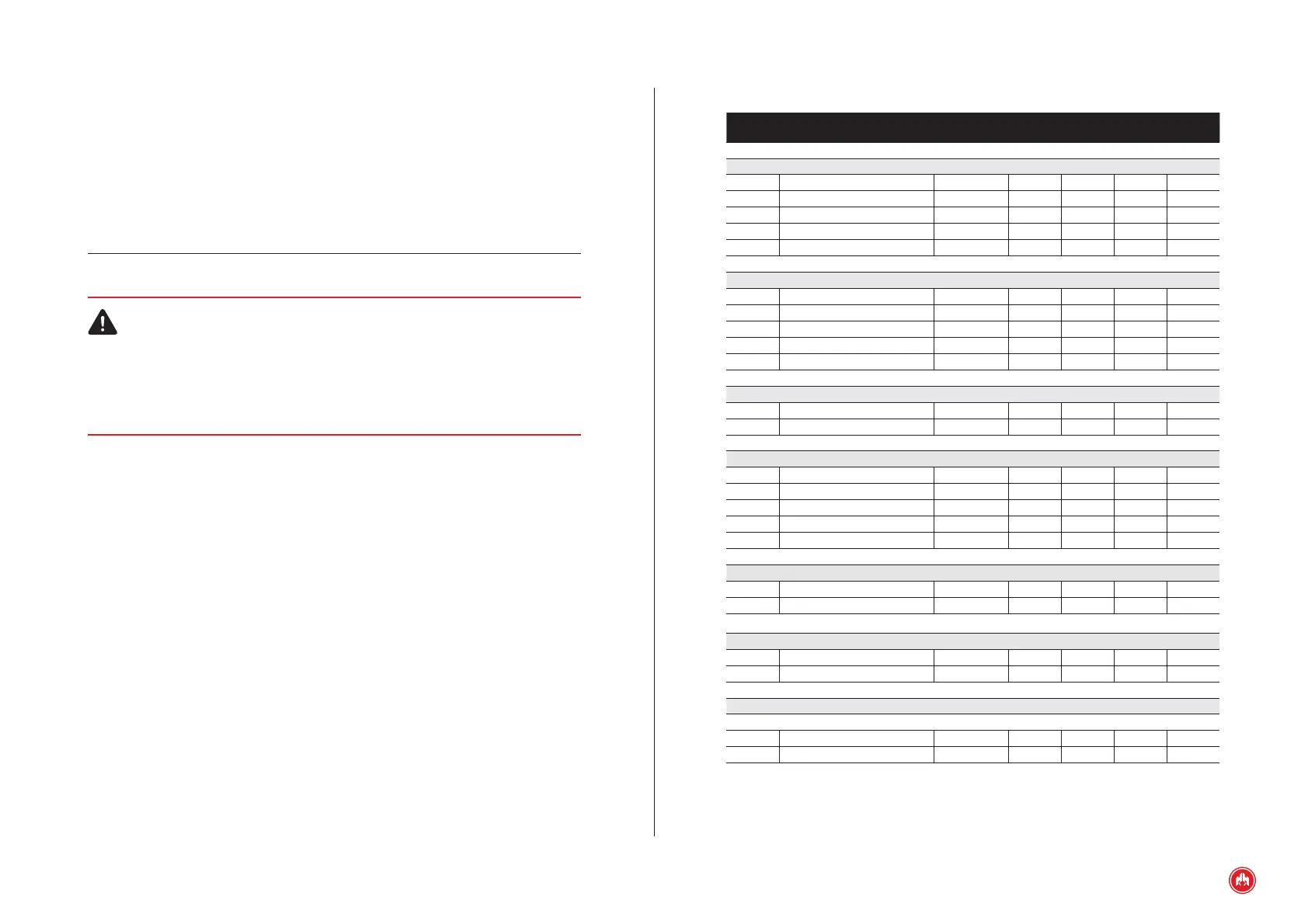
ELECTRICAL CHARACTERISTICS
Symbol Parameter Conditions
Mini-
mum
Typical
Maxi-
mum
Unit
Power supply (terminals 8÷36V, –BAT, +BAT)
8÷36V Module supply voltage 8 36 VDC
+BAT Power supply of the outputs 8 36 VDC
I
BAT
Supply current 8÷36 V=12 V 200 mA
I
BAT
Supply current 8÷36 V=24 V 100 mA
P
BAT
Power consumption 2.5 W
PNP digital input (MAN, AUTO terminal)
V
IN
Input voltage -0.7 36 V
V
IL
Low level input voltage 1 V
V
IH
High level input voltage 5 V
I
IL
Low level input current V
IN
= 0V 0 100 uA
I
IH
High level input current V
IN
= 12V 0.8 1 mA
CAN Bus (terminals CANS, CANL, CANH)
V
IN
Input voltage -58 +58 V
DR
CAN
Baud rate 50 Kbps
NPN digital inputs (terminals PEM, ENT1, ENT2, ENT3)
V
IN
Input voltage -0.7 +36 V
V
IL
Low level input voltage 1 V
V
IH
High level input voltage 5 V
I
IL
Low level input current V
IN
= 0V 2 2.5 mA
I
IH
High level input current V
IN
= 24V 0 100 uA
Analogue inputs for voltage measurement (VRN, VR1, VR2, VR3, VGN, VG1, VG2, VG3 terminals)
V
IN-FF
Input voltage phase to phase 520 VAC
V
IN-FN
Input voltage phase to neutral 300 VAC
Analog current measurement inputs (ILN, IL1, IL2, IL3 terminals)
I
IN
Input current 5 AAC
R
IN
Input resistance 0,02 Ω
Voltage-free relay outputs (CRC, CRNC, CRNA, CGC, CGNC, CGNA, SCC, SCNC, SCNA terminals
)
Power relays
V
O
High voltage relay contacts 250 VAC
I
O
Current relay contacts
cosf = 1
8 A
The disconnecting means must be accessible by the user. The negative terminal
of the battery, the chassis of the electrical panel and the chassis of the genera-
tor set must all be earthed.
The manufacturer is not liable for any damage caused by not following the warn-
ings and / or recommendations indicated in the manual, since the protection en-
sured by the equipment may be compromised.
Maximum height assigned above sea level is 2000m
THIS EQUIPMENT CAN GENERATE RISK OF DAMAGE IF HANDLED IMPROPERLY.
IT MUST BE INSTALLED BY QUALIFIED PERSONNEL.
IT IS NECESSARY TO CONSULT THE DOCUMENTATION OF EQUIPMENT.
ATTENTION: RISK OF DAMAGE.