m
l m
R
c
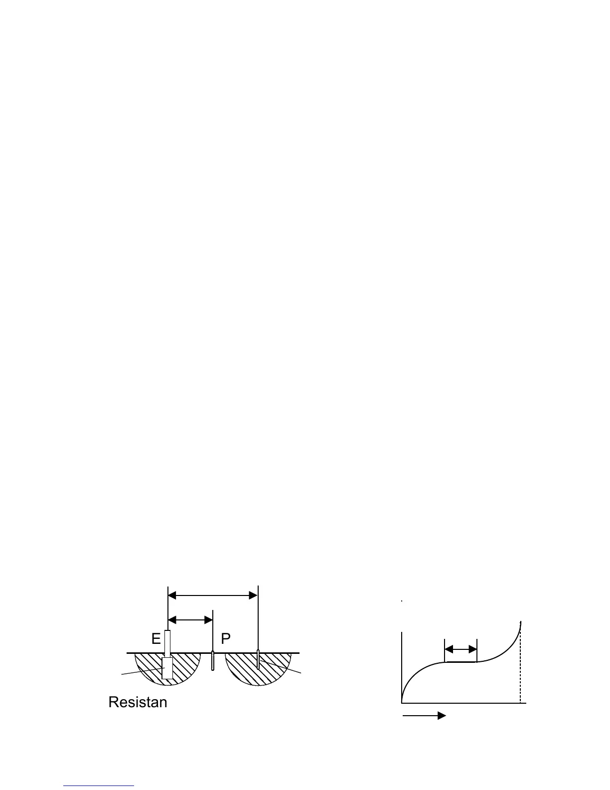
Earth surface
(b)
(a)
When the distance between the electrodes E-
C
is small, the earthing resistance of the
measurement object (Rx) and the auxiliary
earthing rods cannot be separated, leading to a
measurement error.
In the case of an architectural structure which
is grounded over a large area, the resistance
range of the earthing resistance (Rx) in the
figure (a) becomes very wide. This means that
it is necessary to position the auxiliary earthing
rods (
P and C) at a sufficiently large distance
from the earthing body (Rx).
To determine the proper distance, move the
auxiliary earthing rod P towards the auxiliary
earthing rod
C and perform measurement at
several points. Check whether there is an area
where the measured resistance remains
approximately constant also when the auxiliary
earthing rod
P is moved. This corresponds to
the horizontal section in the figure (b).
If such an area cannot be found, the
measurement distance is not sufficient, and the
auxiliary earthing rods
P and C should be
moved further away from measurement object.