13
Chapter 2 Measurement Procedure
NOTE
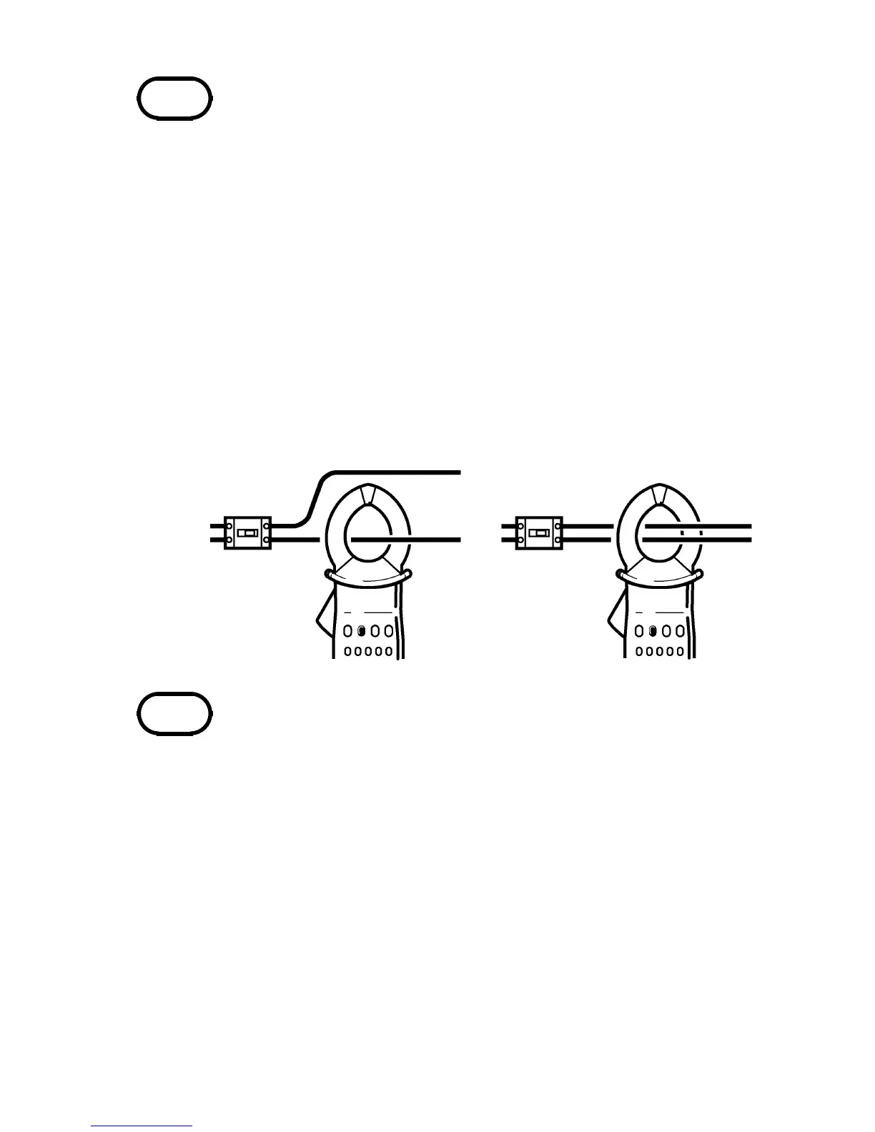
〇
×
NOTE
・ Spurious display indications may be produced
as a result of noise. In this case, enable the
filter function.
・ If the input is less than 1/10 of the full-scale
value, or if the filter function is activated for
measurement of high frequencies, the
frequency indication may not be accurate.
・ The AUTO indication and range indication
show the current range.
【Load current measurement】
Be sure to clamp only one lead of the
conductor.
・ The frequency of special waveforms such as
at the secondary side of an inverter may not
be indicated correctly.
・ Depending on the magnitude and frequency of
the measured current, resonances may be
heard from the clamp jaw. This does not
affect the measurement.
・ When the current to be measured is
unknown, begin measurement with the 200 A
range selected (filter off).
・ Do not input a current which exceeds the
maximum continuous input rating.